Method and system of adjusting a field of view of an interferometric imaging device

a technology of interferometer and field of view, which is applied in the field of methods and systems of imaging, can solve the problems of reducing the number of imaging fibers in the fiber bundle endoscope, limiting the frame rate of lateral scanning single optical fiber probe, and affecting the accuracy of image processing results

Active Publication Date: 2014-08-12
TECHNION RES & DEV FOUND LTD
View PDF26 Cites 14 Cited by
  • Summary
  • Abstract
  • Description
  • Claims
  • Application Information

AI Technical Summary

Problems solved by technology

The harsh size constraints result with reduction of the number of imaging fibers in fiber bundle endoscopes and limit the frame rate of lateral scanning single optical-fiber probes.
By using wavelength information to encode spatial location, SEE images utilize much of the color information to encode spatial location and therefore important color information may be lost.

Method used


Image

  • Method and system of adjusting a field of view of an interferometric imaging device
  • Method and system of adjusting a field of view of an interferometric imaging device
  • Method and system of adjusting a field of view of an interferometric imaging device

Examples


Embodiment Construction

[0039]The present invention, in some embodiments thereof, relates to methods and systems of imaging and, more particularly, but not exclusively, to methods and systems of imaging using optical interferometry.

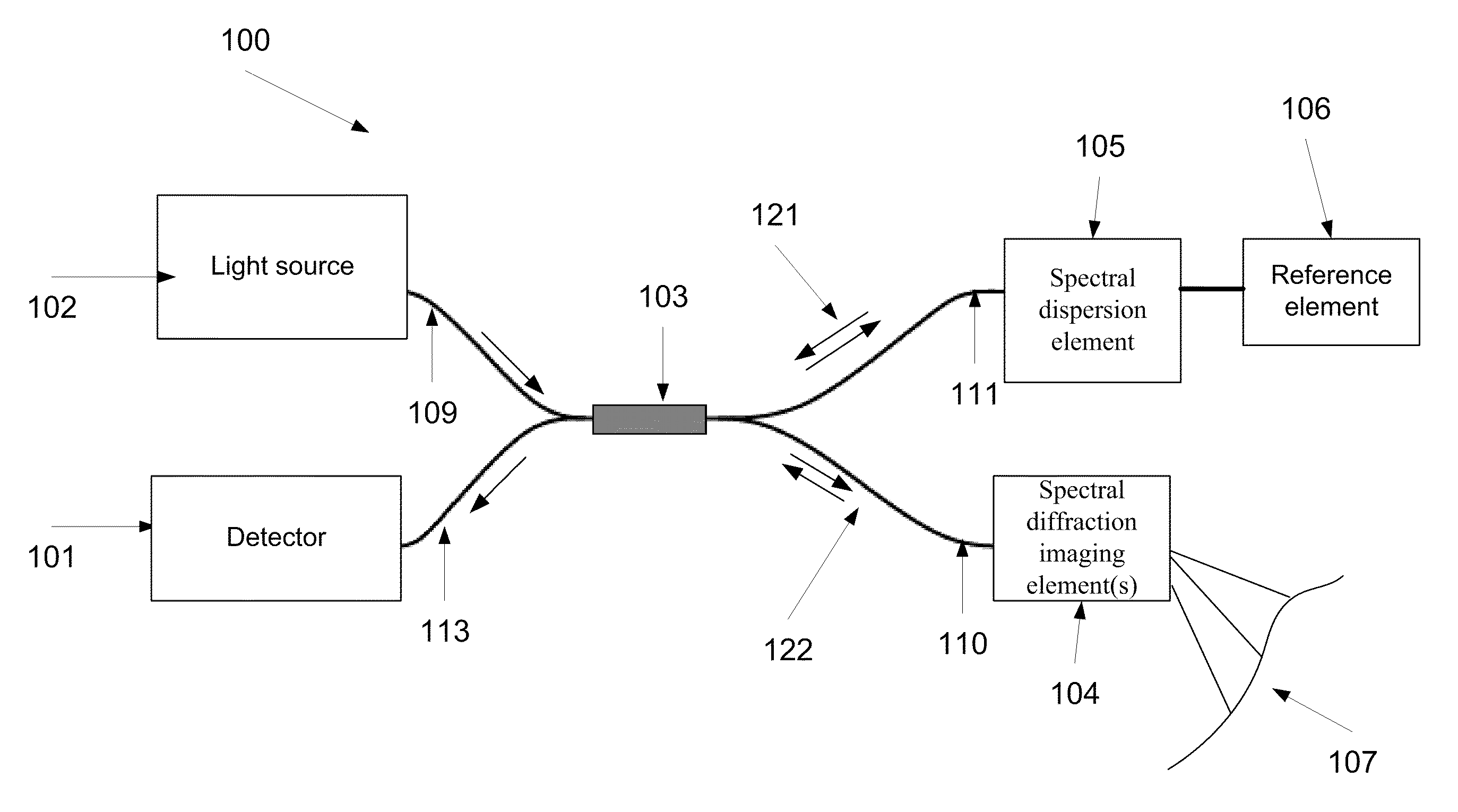
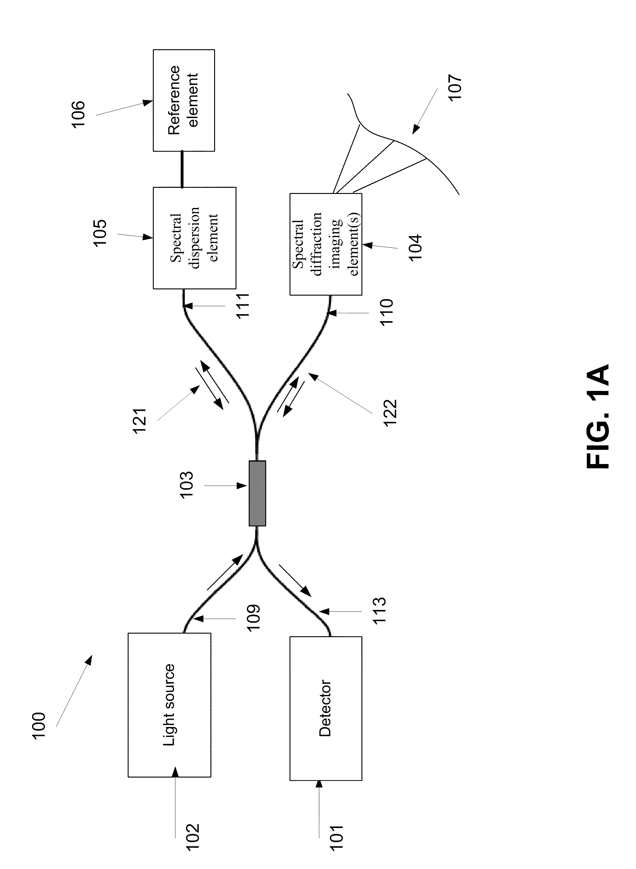
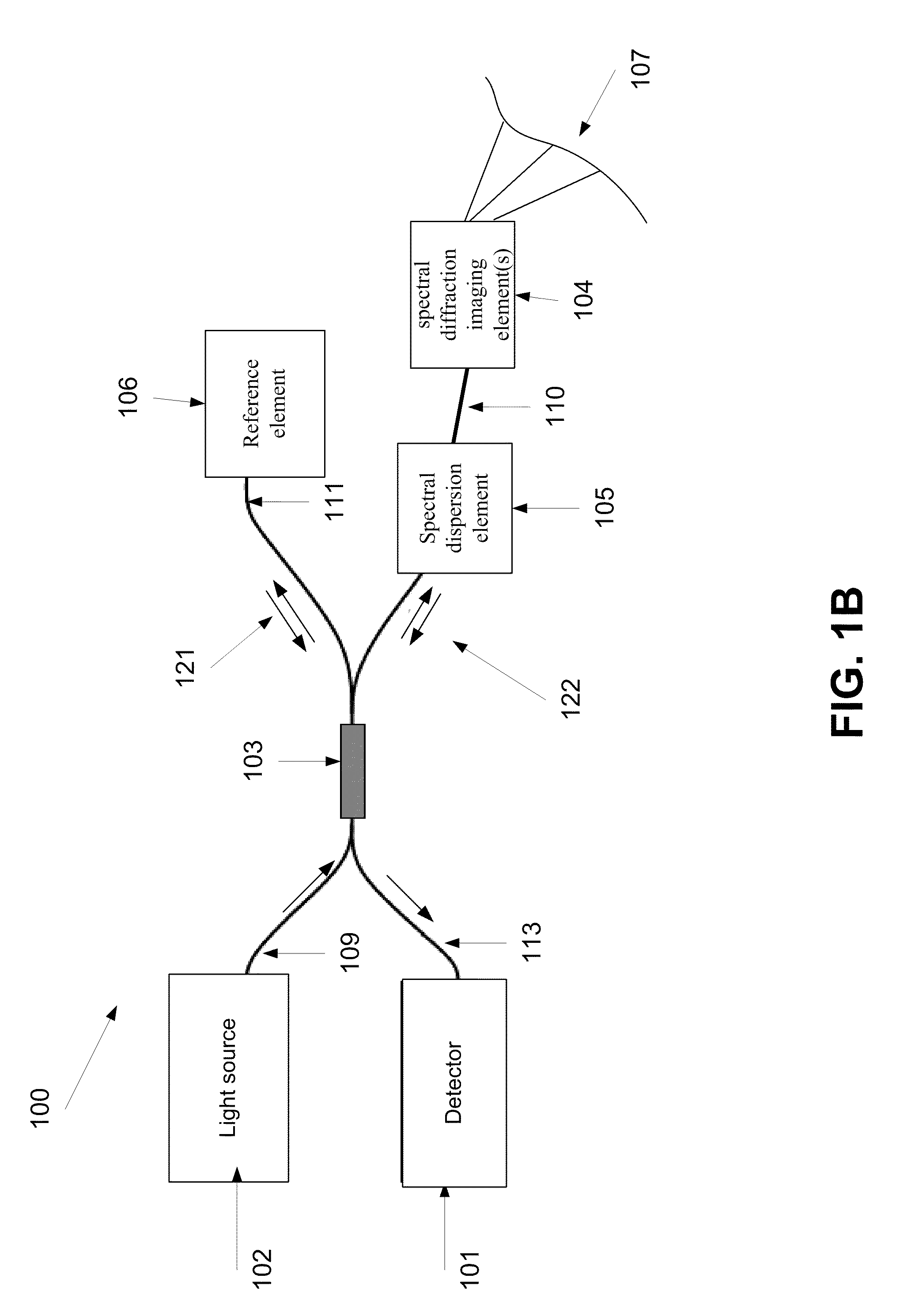
[0040]According to some embodiments of the present invention there is provided an interferometric imaging device, for example an endoscopic or a diagnostic imaging device, with means for adjusting imaging of an object, such as an intrabody surface, by changing the phase of at least one spectral component of light in an interferometric reference and / or imaging arm. The interferometric imaging device includes a beam splitter, which splits a coherent light, optionally received from a coherent light source, such as a laser source, to at least two portions. The device further includes a waveguide which propagates one of the portions toward an imaging spectral dispersion element, such as a diffractive element, for example a grating, which is mounted on its tip so as to spectrally disp...


PUM


Abstract

A method of imaging at least a part of an object. The method comprises splitting electro-magnetic radiation to first and second portions, propagating the first and second portions, spectrally dispersing the first portion toward the part and the second portion toward a reference element, combining between reflections of the spectrally dispersed first and second portions to produce an interference signal, capturing an image of the part from the interference, and adjusting at least one of a tilt of said image plane and a curvature of the image by changing a deviation between the phase of at least one spectral component of the first portion and the phase of at least one spectral component of the second portion.

Description

RELATED APPLICATION[0001]This application claims the benefit of priority under 35 USC 119(e) of U.S. Provisional Patent Application No. 61 / 187,293 filed Jun. 16, 2009, the contents of which are incorporated by reference as if fully set forth herein.FIELD AND BACKGROUND OF THE INVENTION[0002]The present invention, in some embodiments thereof, relates to methods and systems of imaging and, more particularly, but not exclusively, to methods and systems of imaging using optical interferometry. Optical interferometry combines two or more light waves in an optical instrument in such a way that interference occurs between them.[0003]Sub-millimeter diameter endoscopes are being examined for usage in many clinical applications that require minimal tissue damage. The harsh size constraints result with reduction of the number of imaging fibers in fiber bundle endoscopes and limit the frame rate of lateral scanning single optical-fiber probes. Recently, a new method termed spectrally-encoded en...

Claims


Application Information

Patent Timeline
Patent Type & Authority Patents(United States)
IPC IPC(8): G01B9/02
CPCG01B9/02027G01B9/0201G01B9/02044G01B9/0209G01B2290/20
Inventor YELIN, DVIRMERMAN, MICHAL
Owner TECHNION RES & DEV FOUND LTD
Why Eureka
Try Eureka