Optical arrangements for use with an array camera

an array camera and optical arrangement technology, applied in the field of optical arrangement, can solve the problems that the manufacturing techniques of monolithic lenses, polymer-on-glass wlo and wlo have not been adapted for the specific high performance requirements of array cameras, and the wlo technique cannot be used to manufacture array cameras

Inactive Publication Date: 2014-08-12
FOTONATION LTD
View PDF118 Cites 181 Cited by
  • Summary
  • Abstract
  • Description
  • Claims
  • Application Information

AI Technical Summary

Problems solved by technology

However, the standard polymer-on-glass WLO and monolithic lens WLO manufacturing techniques have so far not been adapted for the specific high performance requirements of array cameras.
The flexibility of such choices or processes needs to be increased in order to meet the high demands by array cameras otherwise such WLO techniques cannot be used to manufacture array cameras.

Method used


Image

  • Optical arrangements for use with an array camera
  • Optical arrangements for use with an array camera
  • Optical arrangements for use with an array camera

Examples


embodiment 1

e WLO Design

[0118]Traditional wafer level optics (WLO) is a technology where polymer lenses are molded on glass wafers, potentially on both sides, stacked with further such lens wafers by spacer wafers, and diced into lens modules (this is called “polymer on glass WLO”) followed by packaging of the optics directly with the imager into a monolithic integrated module. As will be described in greater detail below, the WLO procedure may involve, among other procedures, using a wafer level mold to create the polymer lens elements on a glass substrate. Usually this involves incorporating apertures, and in particular the aperture stop by providing openings centered with the later lens channels in an otherwise opaque layer onto the substrate before lens molding.

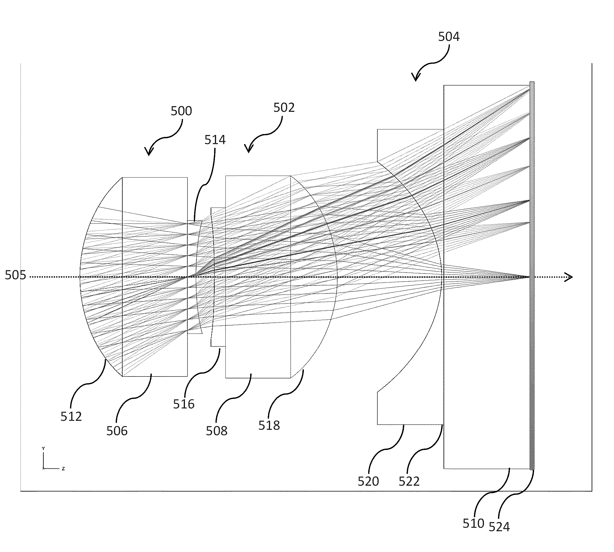
[0119]In a first embodiment, a three-surface optical arrangement suitable for the fabrication by wafer level optics technology, and, in particular, to be used for the optics (as one of the multiple channels) of an array camera is des...

embodiment 3

ens Design with Embedded Substrate

[0168]The embodiments previously discussed dealt with lenses made in accordance with a polymer on glass WLO process. In the following embodiment optical arrangements and designs using a monolithic lens WLO process are provided. In particular, in a first embodiment a monolithic lens stacked with planar substrates for use in forming apertures and filters is described.

[0169]FIG. 6A shows the current state of the art of monolithic lens systems. More or less the same conceptual approach is taken as in creating injection-molded lenses and their packaging. In the state of the art of monolithic lens WLO, many lenses are fabricated on a wafer scale. These replicated lenses 600 are stacked with other previously replicated lens wafers of different topology, the sandwich is diced, and the lens cubes are packaged into an opaque housing 602 with the image sensor 604, which contains the aperture stop 606 at the front as shown in FIG. 6A. This very much limits the ...

embodiment 4

ens Design with Embedded Aperture Stop

[0181]This embodiment of the invention provides yet another alternative for aperture and filter placement within the lens stack of polymer or glass WLO monolithic lenses. As described above with respect to Embodiment 3, the current state of the art for producing monolithic lens optical arrays is to stack the independently replicated monolithic lens wafers, dice the sandwich and package the lens cubes into an opaque housing which contains the aperture stop as an integral part at the front of the array. This methodology limits the degrees of freedom for the optical design of the objective, as well as making it extremely difficult to accurately align the lenses with respect to of the aperture stop.

[0182]Embodiment 3 of the invention described a polymer or glass monolithic lens stacked with substrates for the placement of apertures and filters. In that embodiment of the invention, a substrate, such as glass, having aperture and / or filters thereon is...


PUM


Abstract

A variety of optical arrangements and methods of modifying or enhancing the optical characteristics and functionality of these optical arrangements are provided. The optical arrangements being specifically designed to operate with camera arrays that incorporate an imaging device that is formed of a plurality of imagers that each include a plurality of pixels. The plurality of imagers include a first imager having a first imaging characteristics and a second imager having a second imaging characteristics. The images generated by the plurality of imagers are processed to obtain an enhanced image compared to images captured by the imagers.

Description

RELATED APPLICATION[0001]This application claims priority to U.S. Provisional Application No. 61 / 502,158 filed Jun. 28, 2011, the disclosure of which is incorporated herein by reference.FIELD OF THE INVENTION[0002]The present invention is related to novel optical arrangements, designs and elements for use in an array camera, and more specifically to optical arrangements of varying configurations capable of being used with arrays of image sensors.BACKGROUND OF THE INVENTION[0003]Image sensors are used in cameras and other imaging devices to capture images. In a typical imaging device, light enters at one end of the imaging device and is directed to an image sensor by an optical element such as a lens. In most imaging devices, one or more layers of optical elements are placed before and after the aperture stop to focus light onto the image sensor. Recently array cameras having many imagers and lenses have been developed. In most cases, multiple copies of the optical elements must be f...

Claims


Application Information

Patent Timeline
Patent Type & Authority Patents(United States)
IPC IPC(8): G02B13/00G02B9/12G02B27/10
CPCG02B13/0035G02B13/0085G02B3/0006G02B13/003G02B9/04G02B7/003G02B5/20G02B13/004G02B13/005G02B13/0045B29D11/00298G02B3/0062G02B7/02G02B27/12G02B9/12
Inventor DUPARRE, JACQUES
Owner FOTONATION LTD
Why Eureka
Try Eureka