
System, method and apparatus for recycling quenching medium

a technology of quenching medium and system, applied in heat treatment apparatus, lighting and heating apparatus, cleaning using liquids, etc., can solve the problems of large area, secondary pollution, water waste, etc., and achieve stable quenching quality, small occupied area, and the effect of reducing the workload of quenching medium recycling

Inactive Publication Date: 2014-08-19
FU CHANGZHI +1
View PDF10 Cites 0 Cited by
  • Summary
  • Abstract
  • Description
  • Claims
  • Application Information

AI Technical Summary

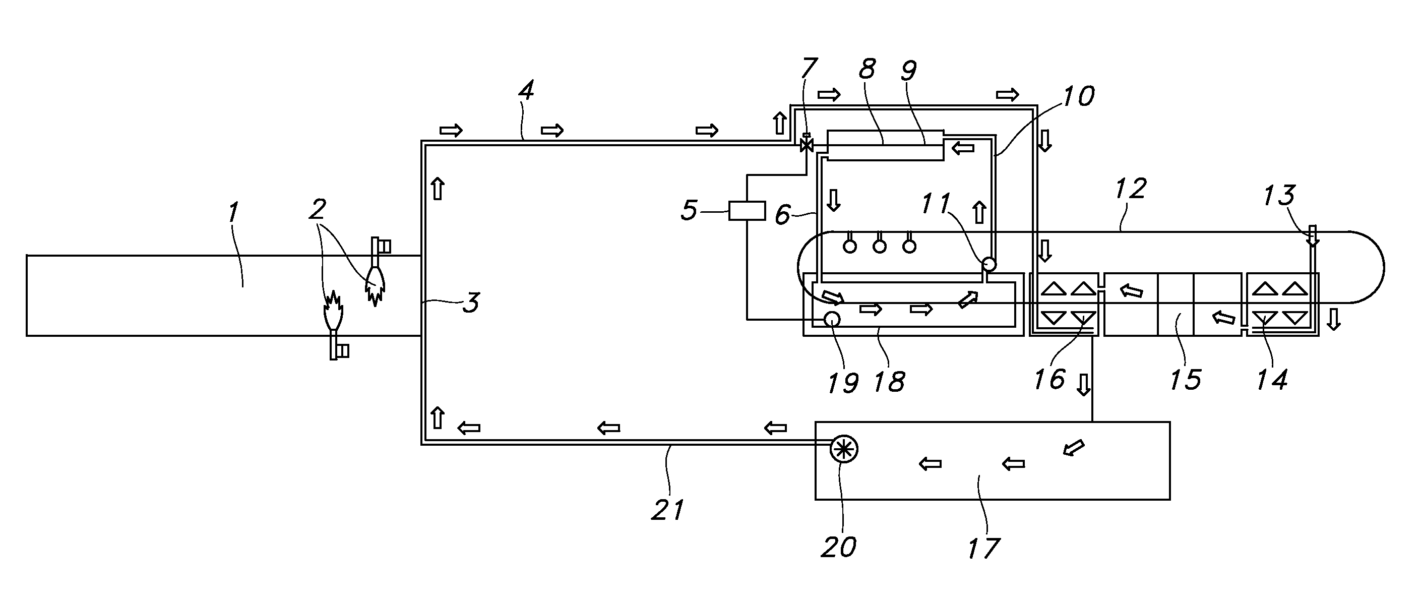
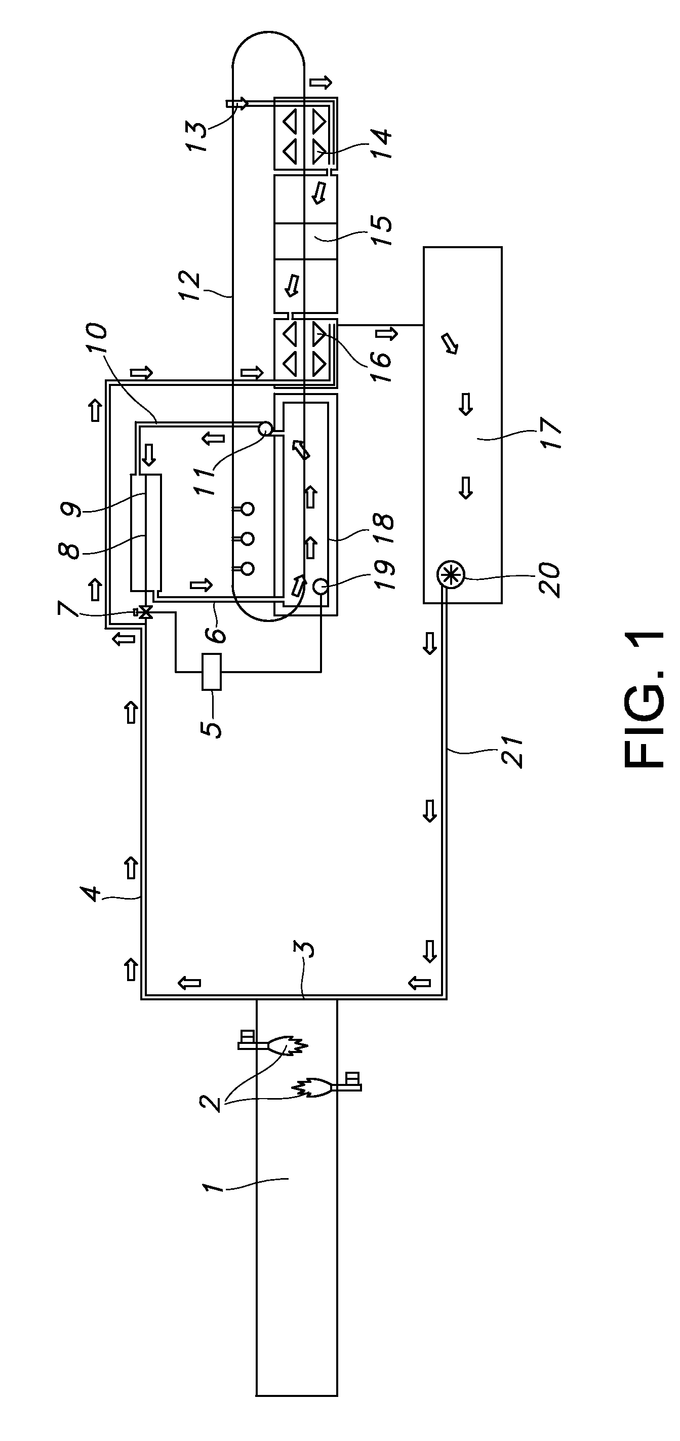
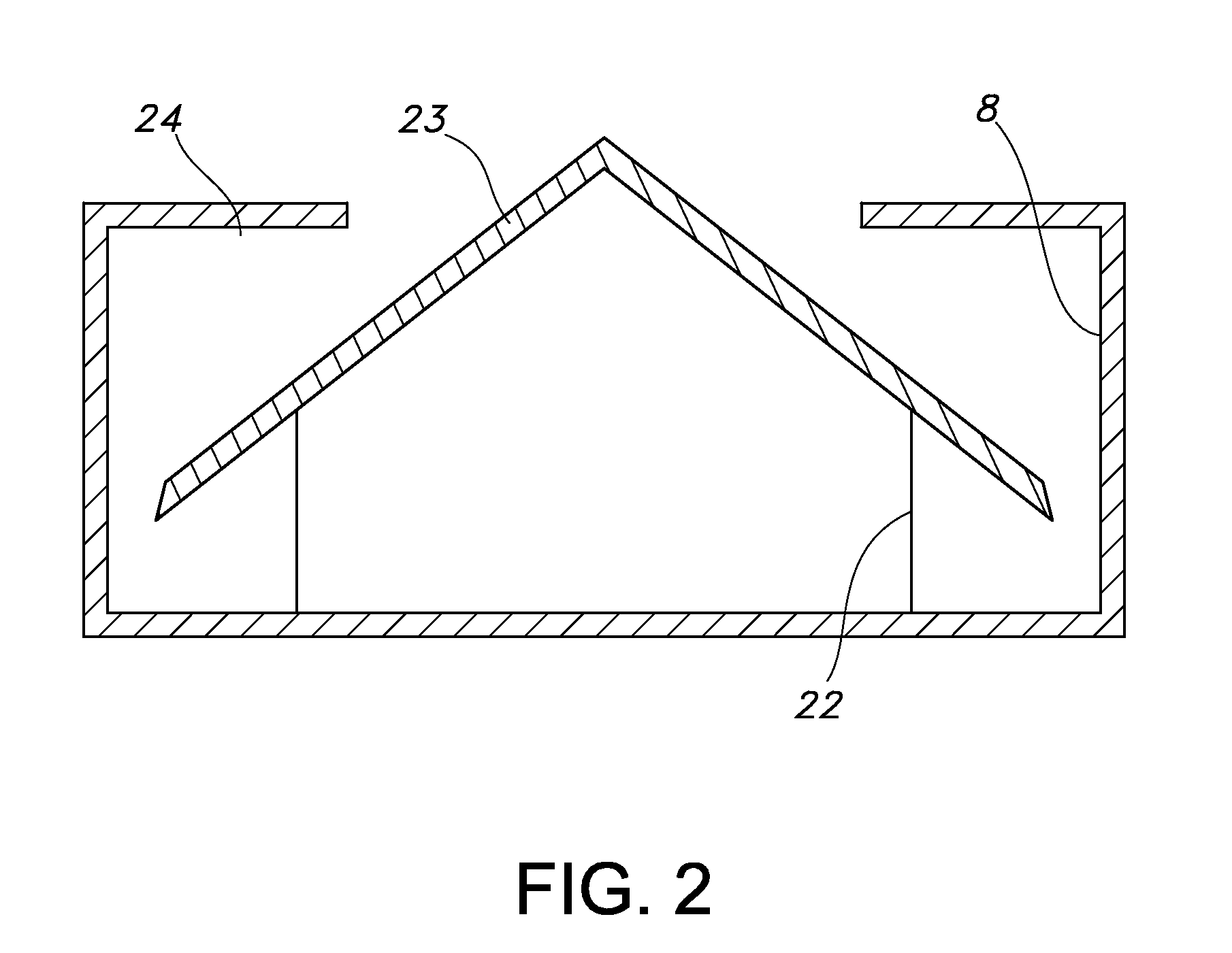
Benefits of technology

The present invention is a new device for recycling quenching medium used in hardware manufacturing. Compared to existing methods, the invention has several advantages such as small area requirement, no water cooling process, automation, no secondary pollution, and efficient cooling and evaporation of spray rinsing water. The quenching medium is automatically recovered and recycled from the molten and mixing tank, which eliminates the need for manual cleaning and drying of the crystal. This saves time, reduces workload, and ensures stable quality. The recovering and recycling process is safe and efficient, making the device environmentally friendly.

Problems solved by technology

The disadvantage of this existing method is, first of all, large area is necessary for drying the medium crystal, and secondly, not only this manual taking out and drying process wastes human labor, also, it can be significantly interrupted by the influence of the natural environment such as unfavorable weather, limitation of space, and additionally, is can cause secondary pollution.
The disadvantages of this existing technique are: first of all, water wasting, and secondly, pipeline blockage by scale deposition, which needs to be regularly maintained and repaired to ensure the quenching quality.

Method used


Image

  • System, method and apparatus for recycling quenching medium
  • System, method and apparatus for recycling quenching medium
  • System, method and apparatus for recycling quenching medium

Examples


Embodiment Construction

[0011]The detailed information of present invention is further described below based on the figures.

[0012]The present invention is metal parts quenching medium recycling apparatus. The preferred embodiments will apply in the production of shovels or other hardware that suits for continuous operation and requires abundant quenching. The design idea is: in order to reduce environmental pollution and medium loss during the metal quenching process, designing a novel functional molten and mixing tank 8, where the spray rinsing water is evaporated by using the heat generated from cooling the quenching medium. The preferred embodiment includes the following steps: transporting the quenching medium in the quenching tank 18 to the molten and mixing tank 8 by using the medium circulation pump 11 and medium delivery pipeline 10; the electromagnetic valve 7 in spray rinsing water by-pass 9 is turn on based on the signal from temperature controller 5, a definite amount of spray rinsing water flo...


PUM

PropertyMeasurementUnit
temperatureaaaaaaaaaa
concentrationaaaaaaaaaa

Abstract

This invention is generally directed to a new metal parts quenching medium recycling apparatus. This device is composed of a heating furnace, a spray rinsing chamber, a immersion cleaning tank, a washing chamber, a liquid storage tank, a quenching chamber and a molten and mixing tank. At one side of a thermal insulation door, a liquid transportation pipeline is connected with the circulation pump that is installed in the liquid storage tank; at another side of the thermal insulation door, a pipeline that transports the spray rinsing water is connected with the spray rinsing chamber. In present invention, the recovering and recycling of quenching media is carried out automatically in the molten and mixing tank, providing a minimized workload and safely procedure to recover and recycle the quenching media. This procedure eliminates both the loss of the quenching media, and the related environmental pollution.

Description

CROSS REFERENCE TO RELATED APPLICATIONS[0001]This application claims the benefit of Peoples' Republic of China application Serial No. 201010269545.4, under 35 USC Sec 119 (a) hereby specifically incorporated by reference in its entirety.FIELD OF INVENTION[0002]This invention is generally directed to metal parts quenching medium recycling apparatus. More specifically, the quenching medium recycling apparatus is to use the heat released from the quenching cooling process to evaporate the spray rinsing water in the quenching medium, in order to recover and recycle the quenching medium.BACKGROUND OF THE INVENTION[0003]In the quenching process for shovel or other hardware that involve large amount of continuous operation, spray rising water and leaching / drip washing water converge into liquid storage tank. Over time, the concentration of quenching medium, as well as the liquid volume increase in the storage tank. In general, there are three temperature levels of liquid storage to recover...

Claims


Application Information

Patent Timeline
Patent Type & Authority Patents(United States)
IPC IPC(8): B08B3/10C21D1/62C21D1/607C21D1/64F28C3/08F28D21/00
CPCC21D1/607F28C3/08F28D21/0001C21D1/64Y02W30/54Y02P10/20
Inventor FU, CHANGZHIFU, YUXUAN
Owner FU CHANGZHI
Learn More