Face milling cutter

a cutter and face technology, applied in shaping cutters, tool workpiece connection, manufacturing tools, etc., can solve the problems of screw holding inserts that tend to loosen, small and medium-sized holes that cannot be machined, and high precision is indispensable. , to achieve the effect of reducing tool breakag

Active Publication Date: 2014-08-19
HANITA METAL WORKS
View PDF46 Cites 14 Cited by
  • Summary
  • Abstract
  • Description
  • Claims
  • Application Information

AI Technical Summary

Benefits of technology

[0018]It is therefore one of the objects of the present application to obviate the limitations of milling cutters and to provide a tooth form which significantly improves metal-removal rates.
[0019]It is a further object of the present application to provide such a face milling cutter with enhanced wear resistance.SUMMARY
[0021]The present application provides an improved form for a rotary cutting tool such as a face end-mill, configured to extend tool life while increasing metal removal rates and reducing tool wear.
[0038]It will be realized from consideration of the provided test results of the cutter that the present application the radially-curved tooth in combination with appropriate rake, clearance and helix angles, and coated, carbide teeth serves to provide a wear-resistant tool that far outlasts milling cutters available presently.
[0039]The use of brazing for attachment of the tungsten carbide cutting portion to the high speed steel body eliminates the holding screw and the holes desired for its passage. Elimination of these holes is most important to minimize tool breakage because the areas surrounding the holes are exposed to the high stress concentrations which lead to tool breakage.

Problems solved by technology

Milling cutters are widely used in milling operations due to their versatile range of application and due to the moderate first cost of the tool.
Two known problems with regard to screw-on inserts are that high precision in positioning the insert is desired to restrict or minimize making over-size holes, and the screw holding the insert has a tendency to loosen due to vibration of the tool when in use.
Yet a further problem regarding tools using two inserts is that high precision is indispensable in the settings of the two inserts which should be identical.
Due to the size of the insert which should be large enough to allow setting and clamping, small and medium size holes can not be machined.
The obvious problem here is that the polished area will not survive for more than a few minutes of work.
Such tests have rarely been carried out due to the high expense involved.
Presently, most inventors test run the form of their choice in a workshop, but even where machining test results are published, conditions of machining (material hardness, cutter diameter and material, number of teeth, machine rigidity, machining speed and feed, coolant composition, surface finish quality, whether the milling cutter is nitride coated or not, and yet further factors) are not standardized and can not be compared.
In the absence of comparative test results it is difficult to assess the merits of prior-art disclosures regarding tooth shapes.
However, for cutting tool steel, a frequent requirement in the manufacture of dies, punches, casting dies, forging dies and press tools, feed rates drop sharply, vibrations are generated and tool breakage occurs.

Method used


Image

  • Face milling cutter
  • Face milling cutter
  • Face milling cutter

Examples


Embodiment Construction

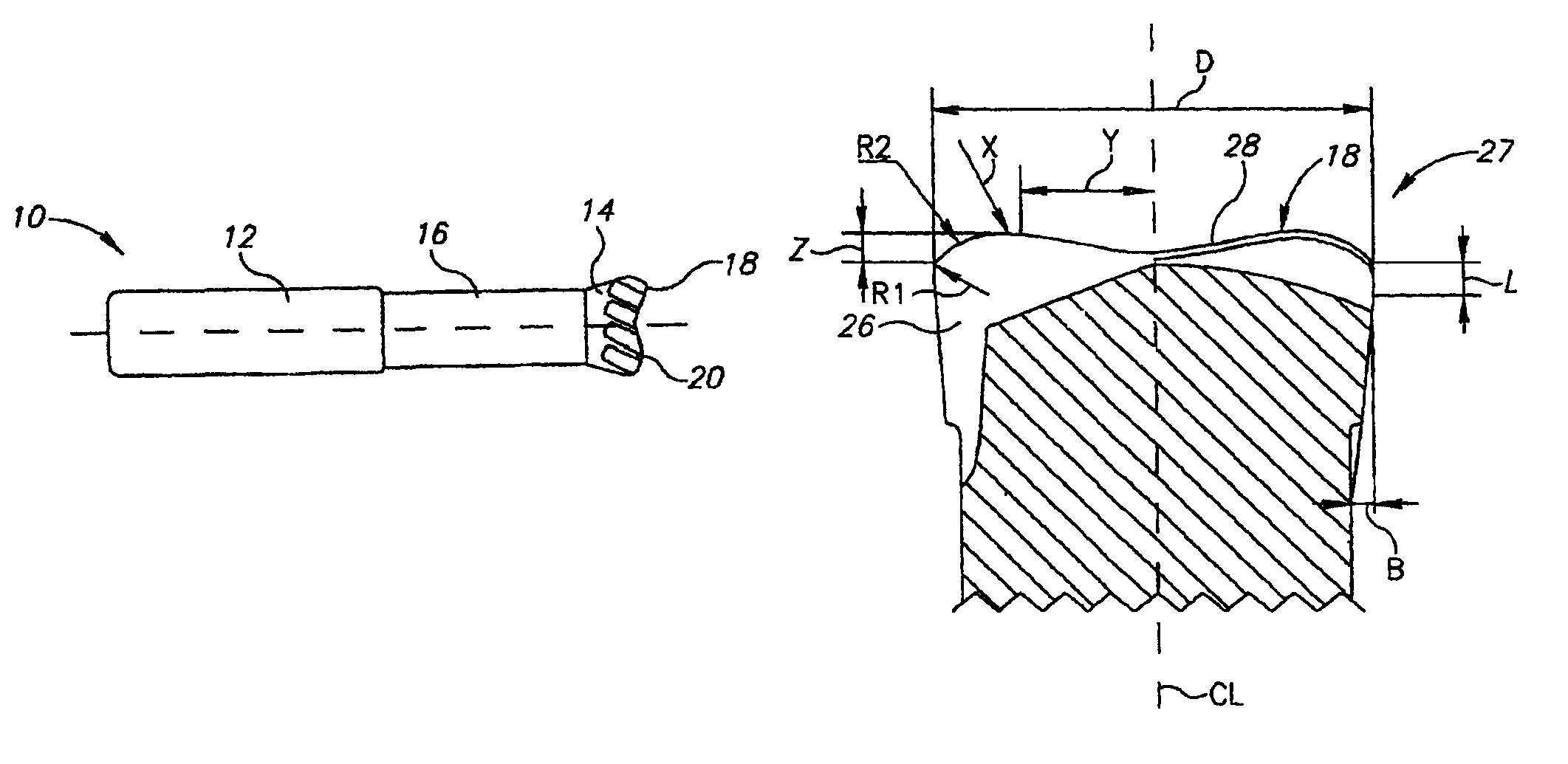
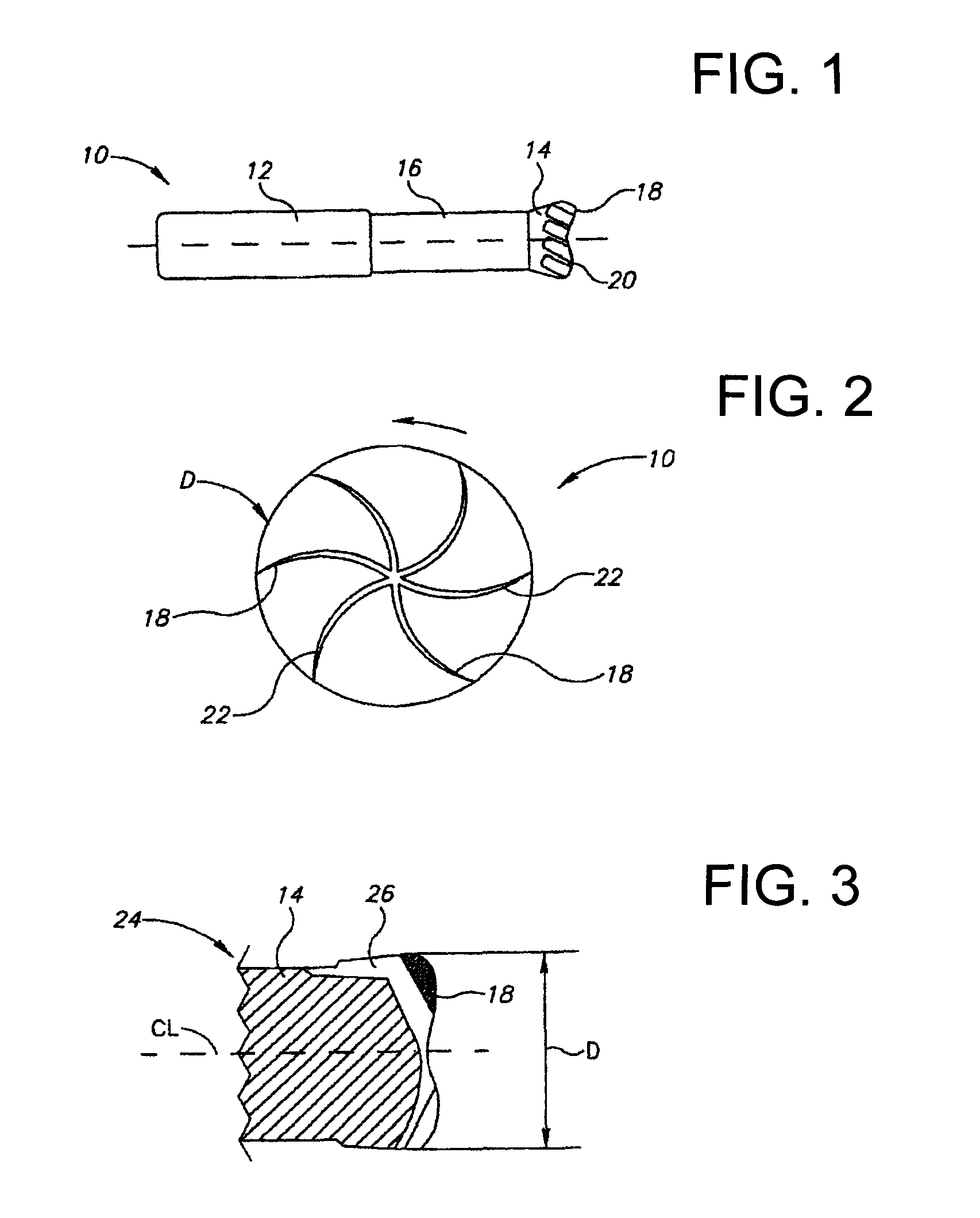
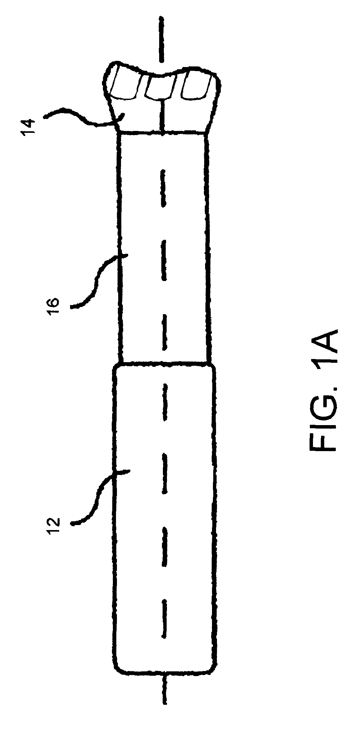
[0065]There is seen in FIGS. 1 and 2 a milling cutter 10 for fast metal removal having a shank portion 12 connected to a cutting portion 14 by a neck portion 16. The cutting portion 14 terminates in a plurality of end cutting edges 18 positioned substantially radially from the axis of the milling cutter, the end cutting edges 18 being curved at least along part of their length as viewed facing the end 20 of the milling cutter cutting portion 14.

[0066]In one possible embodiment of the present application, the diameter of the shank portion 12 of the milling cutter 10 is about one hundred twelve and a half percent of the diameter of the neck portion 16. At the largest circumference of the cutting portion 14, the cutting portion 14 is about one hundred thirty-three percent of the diameter of the neck portion 16.

[0067]The tooth of cutting portion has a depth of about 0.1 D at each side of the outer diameter D, leaving a core equal to about 0.8 D. In combination with the short flutes, the...


PUM


Abstract

A face milling cutter has a shank portion adjoining a cutting portion. The cutting portion terminates in a plurality of cutting edges extending in a radial direction from a central axis of the face milling cutter. The cutting edges are convexly curved at least along a part of their length. A portion of the cutting edges proximate the central axis is nearer in an axial direction to the shank portion than a point, X, on the cutting edges that is farthest away from the shank portion. A distance Y, between the point, X, and the central axis is between 20% and 40% of a diameter, D, of the face milling cutter, and a central portion extends the distance, Y, and has a radius of curvature of about 110% of the diameter, D.

Description

CONTINUING APPLICATION DATA[0001]This application is a Continuation-In-Part application of International Patent Application No. PCT / IL2007 / 000409, filed on Mar. 29, 2007, which claims priority from Israeli Patent Application No. 174775, filed on Apr. 4, 2006. International Patent Application No. PCT / IL2007 / 000409 was pending as of the filing date of this application. The United States was an elected state in International Patent Application No. PCT / IL2007 / 000409.BACKGROUND[0002]1. Technical Field[0003]The present application relates to tools for the machining of materials by milling.[0004]2. Background Information[0005]Background information is for informational purposes only and does not necessarily admit that subsequently mentioned information and publications are prior art.[0006]Milling cutters are widely used in milling operations due to their versatile range of application and due to the moderate first cost of the tool. Milling cutters are often of cylindrical shape, and are av...

Claims


Application Information

Patent Timeline
Patent Type & Authority Patents(United States)
IPC IPC(8): B23P15/34
CPCB23C5/10B23C2210/084B23C2240/08B23C2265/08Y10T407/1946Y10T407/1952Y10T407/1962Y10T407/1964Y10T407/196Y10T407/1948Y10T407/14
Inventor VOLOKH, VLADIMIRBOULAKHOV, SERGEIZEIDNER, SHAYSHARIVKER, LEONID
Owner HANITA METAL WORKS
Why Eureka
Try Eureka