Fixed type constant velocity universal joint

a constant velocity, universal joint technology, applied in the direction of yielding couplings, couplings, rotary machine parts, etc., can solve the problems of reducing durability, heat generation in the joint, and reducing durability, so as to improve productivity, reduce cost, and high accuracy

Active Publication Date: 2014-08-19
NTN CORP
View PDF20 Cites 1 Cited by
  • Summary
  • Abstract
  • Description
  • Claims
  • Application Information

AI Technical Summary

Benefits of technology

[0042]In the fifth fixed type constant velocity universal joint and the sixth fixed type constant velocity universal joint, the outer surface of the inner joint member does not contact to the inner spherical surface of the cage, and in the fourth fixed type constant velocity universal joint, a contact area is small even when the outer surface of the inner joint member is brought into contact with the inner spherical surface of the cage. Therefore, in those fixed type constant velocity universal joints, the outer surface of the inner joint member and the inner spherical surface of the cage do not need to be subjected to high accuracy working such as grinding after heat treatment or hardened steel cutting. Thus, the cost can be reduced and the productivity can be improved.
[0043]The number of balls to be used is generally six, but the present invention is also applicable to a fixed type constant velocity universal joint using eight or ten balls. When the number of balls is increased as described above, the joint can be reduced in size and weight while securing the load capacity.
[0044]When the curvature centers of the track grooves of the outer joint member and the inner joint member a

Problems solved by technology

Therefore, when the joint is subjected to high load or rotated at high speed, this contact causes heat generation in the joint, and the durability may reduce.
However, even with such a structure, when the joint is subjected to high load or during high-speed rotation, h

Method used


Image

  • Fixed type constant velocity universal joint
  • Fixed type constant velocity universal joint
  • Fixed type constant velocity universal joint

Examples


Embodiment Construction

[0097]Hereinafter, embodiments of the present invention are described with reference to FIGS. 1 to 47.

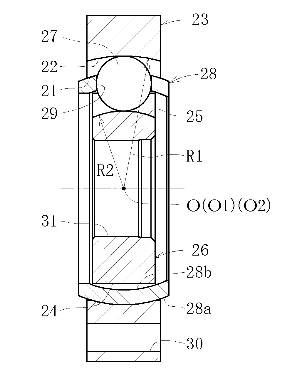
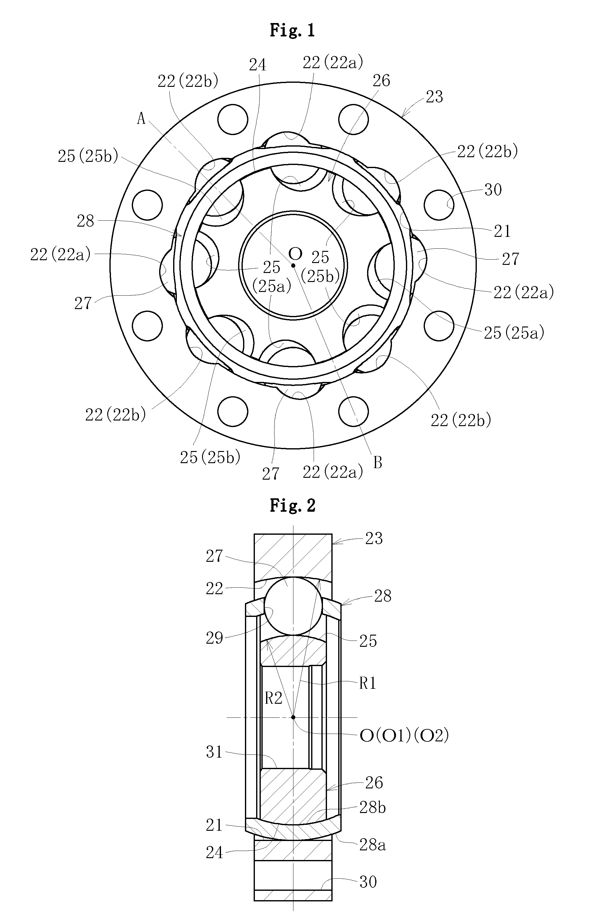
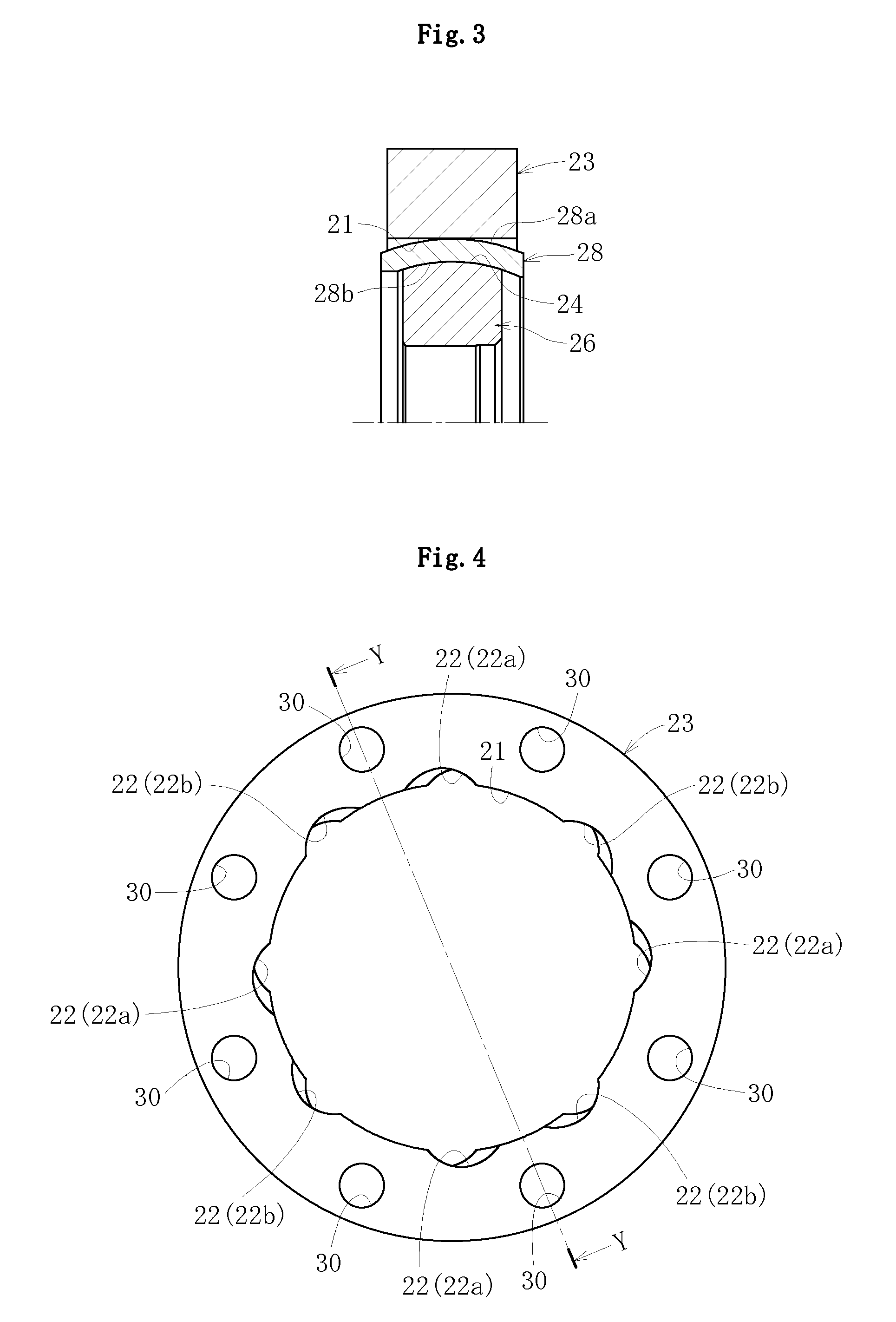
[0098]A fixed type constant velocity universal joint according to a first embodiment of the present invention includes, as illustrated in FIGS. 1 and 2: an outer race 23 having an inner surface 21 in which a plurality of (eight) track grooves 22 are formed along an axial direction, the outer race 23 serving as an outer joint member; an inner race 26 having an outer surface 24 in which a plurality of (eight) track grooves 25 are formed along the axial direction, the inner race 26 serving as an inner joint member; a plurality of (eight) torque transmitting balls 27 arranged in ball tracks formed of pairs of the track grooves 22 of the outer race 23 and the track grooves 25 of the inner race 26; and a cage 28 interposed between the inner surface of the outer race 23 and the outer surface of the inner race, for retaining the torque transmitting balls.

[0099]Each of the track grooves 22 o...


PUM


Abstract

A fixed type constant velocity universal joint prevents heat generation when a high load is applied or during high-speed rotation to improve durability, and suppresses a contact resistance between a cage and inner and outer races to improve constant velocity performance. Curvature centers of track grooves of outer and inner joint members have an offset of 0 in an axial direction. Track grooves of the outer and inner joint members, which are tilted in opposite directions from each other with respect to an axis line, are alternately formed in a circumferential direction. An outer surface of the inner joint member is a spherical surface to be brought into sliding contact with an inner spherical surface of the cage. An inner surface of the outer joint member is a cylindrical surface.

Description

BACKGROUND OF THE INVENTION[0001]1. Technical Field[0002]The present invention relates to a constant velocity universal joint which is used in, for example, a power transmission system for automobiles and various industrial machines.[0003]2. Background Art[0004]For example, a fixed type constant velocity universal joint can be taken as an example of a constant velocity universal joint used as means for transmitting a rotational force from an engine to wheels of an automobile at a constant velocity. The fixed type constant velocity universal joint has a structure in which two shafts, a driving shaft and a driven shaft, are coupled to each other and which is capable of transmitting rotational torque at a constant velocity even when the two shafts form an operating angle. Generally, a Birfield type (BJ) constant velocity universal joint and an undercut-free type (UJ) constant velocity universal joint have been widely known as the above-mentioned constant velocity universal joint.[0005]...

Claims


Application Information

Patent Timeline
IPC IPC(8): F16D3/227F16D3/223F16D3/224F16D3/2245
CPCF16D3/223F16D3/2245F16D3/224F16D2003/22309F16D2003/22303Y10S464/906
Inventor FUJIO, TERUAKISUGIYAMA, TATSURO
Owner NTN CORP
Why Eureka
Try Eureka