Rotating machinery condition monitoring using position sensor

a position sensor and rotating machine technology, applied in the direction of frequency analysis, vibration measurement in solids, emergency protective arrangements for automatic disconnection, etc., can solve the problems of repeated encountering of machines, undesirable vibrations in rotating machines, and acceleration of failure of worn or another, component of rotating machines

Active Publication Date: 2014-08-19
ROCKWELL AUTOMATION TECH
View PDF12 Cites 11 Cited by
  • Summary
  • Abstract
  • Description
  • Claims
  • Application Information

AI Technical Summary

Problems solved by technology

Because a rotating machine repeatedly travels over a closed, rotational path, the machine will repeatedly encounter any problem that develops in that path.
Many such conditions establish undesirable vibrations in the rotating machine.
The vibrations may, in turn, accelerate failure of the worn, or another, component of the rotating machine.
However, the use of accelerometers has various disadvantages.
In addition, the accelerometer is typically not utilized for control of the rotating machine and is, therefore, not included on the machine.
Consequently, using accelerometers to monitor performance of the rotating machine typically creates an additional expense and requires on-site installation to identify problems after they arise in the field.
Another challenge faced when performing vibration analysis is that the rotating machine must typically be operated at a constant speed to perform the vibration analysis.

Method used


Image

  • Rotating machinery condition monitoring using position sensor
  • Rotating machinery condition monitoring using position sensor
  • Rotating machinery condition monitoring using position sensor

Examples


Embodiment Construction

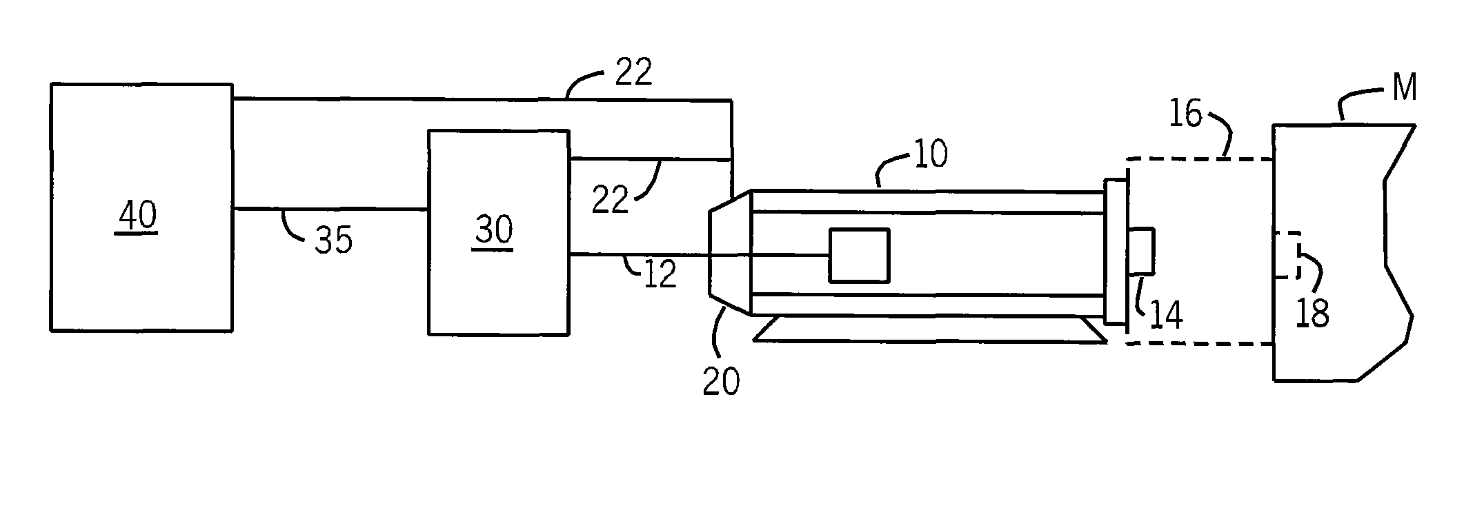
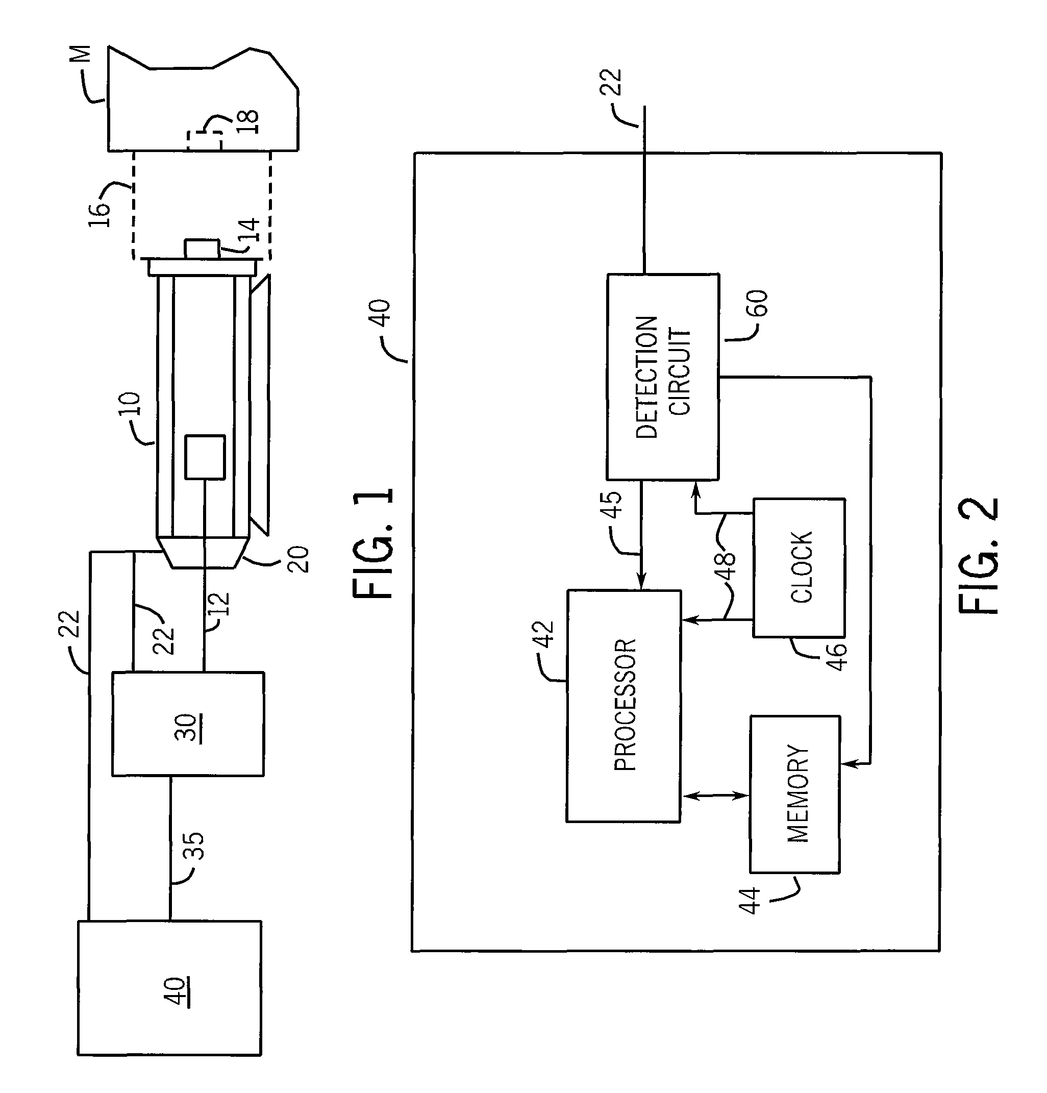
[0019]Turning initially to FIG. 1, an exemplary environment for controlling rotating machinery is illustrated. An industrial controller 40 is connected to a motor drive 30 which is controlling operation of a motor 10. The industrial controller 40 may be, but is not limited to an industrial computer or a programmable logic controller (PLC). Optionally, the industrial controller 40 may be integral to the motor drive 30. The industrial controller 40 executes a program to generate a reference signal 35 which is communicated to the motor drive 30. The reference signal 35 may be, but is not limited to, a speed or a torque command. In response to the reference signal 35, the motor drive 30 generates an output voltage 12 suitable for controlling operation of the motor 10. The voltage may be either an Alternating Current (AC) or a Direct Current (DC) voltage according to the requirements of the machine 10. Optionally, the voltage may be supplied directly from a utility input or a separate po...


PUM


Abstract

Continuous monitoring and fault diagnosis of rotating machinery during variable speed operation is performed using only a position feedback signal. The position sensor generates a periodic waveform having multiple pulses per revolution of the machine. A circuit is included to detect, for example, a zero crossing or edge of the periodic waveform. At each detected zero crossing or edge, the time and position of the event is stored in memory. Other data, such as the current in the motor, may also be sampled and stored in memory. Because the sampled data is triggered by repeated feature of the position feedback signal, the sampled data is in a stationary reference frame in the position domain. Frequency analysis is performed on the sampled data, and the frequency components present in either the sampled signal are analyzed to identify the presence of a fault in the rotating machinery.

Description

BACKGROUND OF THE INVENTION[0001]The subject matter disclosed herein relates to monitoring the condition of rotating machinery, such as electric motors, and, more specifically, to monitoring the condition of rotating machinery during operation at either constant or variable speed using a position sensor.[0002]Because a rotating machine repeatedly travels over a closed, rotational path, the machine will repeatedly encounter any problem that develops in that path. For example, if a portion of a bearing in a motor becomes worn, the rotor will repeatedly travel over the worn surface. Many such conditions establish undesirable vibrations in the rotating machine. The vibrations may, in turn, accelerate failure of the worn, or another, component of the rotating machine. In addition, certain types of faults develop vibrations having unique and identifiable frequency components. Thus, it is desirable to monitor vibrations in rotating machine to monitor overall performance of the machine and ...

Claims


Application Information

Patent Timeline
Patent Type & Authority Patents(United States)
IPC IPC(8): H02P6/16
CPCH02P29/021H02P29/0241
Inventor LI, LINGLAIQIAN, WEILUNDELL, THOMAS D.
Owner ROCKWELL AUTOMATION TECH
Why Eureka
Try Eureka