Steam injected gas turbine engine

a gas turbine engine and steam injection technology, applied in the direction of machines/engines, mechanical equipment, lighting and heating apparatus, etc., can solve the problems of difficult control of steam placement to the conditions required for combustion and cooling, and achieve the effect of improving the flexibility of steam injection placemen

Active Publication Date: 2014-08-26
ROLLS ROYCE PLC
View PDF10 Cites 2 Cited by
  • Summary
  • Abstract
  • Description
  • Claims
  • Application Information

AI Technical Summary

Benefits of technology

[0006]It would be desirable to improve the flexibility of placement of steam injection in advanced cycle engines. In particular, steam injected into the vicinity of the outlet of the compressor section can make it difficult to control steam placement to the conditions required for combustion and cooling.
[0012]Advantageously, the reservoir provides a means of temporarily storing steam, thereby smoothing the flow of steam to the combustion chamber. By providing the reservoir at the upstream end of the combustion chamber, the steam may be stored close to where it is to be injected, and may provide a system that can be relatively easily adjusted or reconfigured as needed to alter the position or amount of flow of steam into the combustion zone. That is, a high degree of flexibility in the location and configuration of outlet ports from the reservoir into the combustion chamber can be achieved. Further, outlets of the reservoir can help to modify the momentum of the steam. For example, the steam can be injected via a low momentum flow whereby the steam's momentum can be matched more closely to the momentum of the combustion gases in the combustion chamber, which reduces the impact of the injected steam on the fluid dynamics of the combustion process. Alternatively, the reservoir can be used to provide a more disruptive high momentum steam injection which can be used to improve mixing within and upstream of the combustion chamber.
[0015]Typically, the steam reservoir has one or more inlet ports for receiving steam from the steam generator, and one or more outlet ports for delivering the received steam into the combustion zone. Conveniently, the reservoir can have fewer inlet ports than outlet ports. The reservoir can thus serve as a manifold, distributing the received steam to the outlet ports. Advantageously, this allows the number pipes carrying steam into the engine to be reduced. In particular, multiple penetrations of the casing of the combustion chamber can be avoided, such multiple penetrations giving rise to external piping congestion, and often requiring strengthening of the casing with an adverse cost implication.
[0019]Conveniently, the combustion chamber may have one or more mounting pins which mount the combustion chamber at a radially outer side thereof to the engine, and which penetrate to the steam reservoir, the or each pin containing an internal flow passage which extends between an opening at an outer end of the pin to an opening which forms an inlet port to the reservoir, whereby the steam received by the reservoir is routed thereto through the flow passage. As mounting pins are conventional mounting architecture for combustion chambers, substantial reconfiguration of the engine can once again be avoided.
[0022]When the combustion chamber is the combustion chamber of an annular combustor, the steam reservoir may be formed as an annulus which extends circumferentially around the upstream end of the combustion chamber. The reservoir can extend continuously around the annulus. Alternatively, the steam reservoir may be divided by internal walls into self-contained, circumferentially arranged, reservoir portions. Steam flow into and out of each portion can then be controlled independently of the other portions. For example, the combustion chamber typically has a plurality of circumferentially spaced fuel injectors, and each reservoir portion can then be formed around a respective fuel injector. The different reservoir portions can be controlled appropriately depending on the flame or staging statuses of their fuel injectors. Having different reservoir portions can also provide a means of mitigating rumble or compensating for local combustor liner degradation.
[0026]In another example, the combustion chamber may have one or more fuel injectors, each having a fuel nozzle and an air swirler which swirls an airflow around fuel sprayed from the nozzle, and the reservoir my have one or more diverter passages that allow fluid communication with the airflow directed to the swirler, the flow passages being adapted such that, when the steam reservoir receives steam from the steam generator, the steam pressure prevents the airflow entering the reservoir, but, when the steam reservoir does not receive steam from the steam generator, the airflow enters the reservoir and is delivered therefrom into the combustion chamber. This arrangement allows the reservoir to be filled with air when steam may not be available (e.g. at start up). The flow pattern out of the reservoir can thus be maintained, albeit with air, when there is no steam. Further, cooling, e.g. of a base plate of the type as discussed above, can be maintained.

Problems solved by technology

In particular, steam injected into the vicinity of the outlet of the compressor section can make it difficult to control steam placement to the conditions required for combustion and cooling.

Method used


Image

  • Steam injected gas turbine engine
  • Steam injected gas turbine engine
  • Steam injected gas turbine engine

Examples


Embodiment Construction

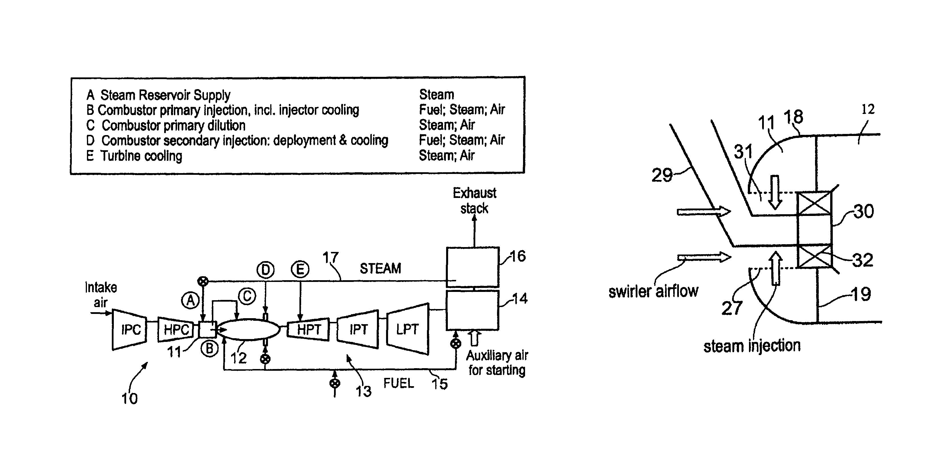
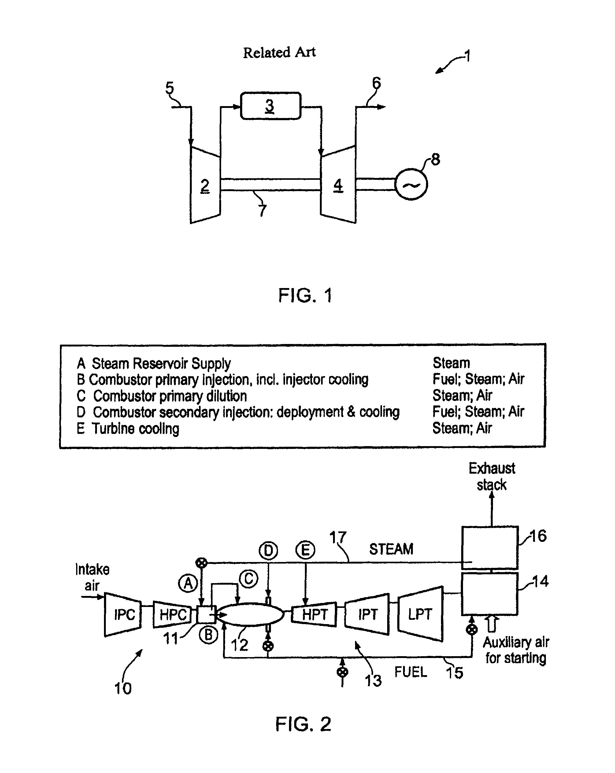
[0043]FIG. 2 shows schematically an industrial gas turbine engine according to the present invention, and indicates the main feed routes for steam and fuel. The engine comprises, in flow series through the engine: a compressor section 10 comprising an intermediate pressure compressor (IPC) and a high pressure compressor (HPC); combustor comprising a steam reservoir 11 and a combustion chamber 12; a turbine section 13 comprising a high pressure turbine (HPT), an intermediate pressure turbine (IPT) and a low pressure turbine (LPT); and an exhaust duct burner 14. The IPC and IPT are connected by a shaft, and the HPC and HPT are connected by another, coaxial, shaft. The LPT drives a generator (not shown). A fuel feed 15 supplies fuel to primary and secondary injection positions of the combustion chamber. The fuel feed also supplies fuel to the exhaust duct burner. Heat is extracted from the burner by a boiler 16 and used to generate steam, which is sent to a steam feed 17. Some of the s...


PUM


Abstract

A gas turbine engine has in flow series: a compressor section, a combustion chamber, and a turbine section. The engine further has a steam generator. The combustion chamber has a steam reservoir located at the upstream end thereof. The steam reservoir receives steam from the steam generator, and delivers the received steam into a combustion zone of the combustion chamber.

Description

FIELD OF THE INVENTION[0001]The present invention relates to a gas turbine engine in which steam is injected into a combustion chamber.BACKGROUND OF THE INVENTION[0002]FIG. 1 shows schematically a conventional industrial gas turbine engine 1 which comprises, in flow series through the engine, a compressor section 2, a combustor 3, and a turbine section 4. The engine works in a conventional manner so that air entering an intake 5 of the engine forms a flow into the compressor section, which compresses the flow before delivering the compressed air into the combustor where it is mixed with fuel and the mixture combusted. The resultant hot combustion products then expand through and thereby drive the turbine section before being exhausted through an exhaust 6. The turbine section is mounted on a shaft or coaxial shafts 7 with the compressor section and a generator 8. Power extracted from the working gas by the turbine section drives the compressor section and the generator.[0003]Steam i...

Claims


Application Information

Patent Timeline
Patent Type & Authority Patents(United States)
IPC IPC(8): F02C7/00F02C3/30F02C6/18F23L7/00F23R3/04F23R3/28
CPCF23R3/04F02C3/305F02C6/18F02C3/30F23R3/283F23L7/005F05D2270/082
Inventor FLETCHER, PAULGRAHAM, ANDREW CHARLESMORAN, JOHNNEESON, CHRISTOPHER
Owner ROLLS ROYCE PLC
Why Eureka
Try Eureka