Marine vessel propulsion device

a propulsion device and marine technology, applied in the direction of marine propulsion, motor-driven power plants, vessel construction, etc., can solve the problems of complex structure of the marine propulsion device, and achieve the effects of increasing the electric current generated in the power generation coil, reliable supply, and greater electrical power supplied to the stator

Active Publication Date: 2014-08-26
YAMAHA MOTOR CO LTD
View PDF9 Cites 7 Cited by
  • Summary
  • Abstract
  • Description
  • Claims
  • Application Information

AI Technical Summary

Benefits of technology

[0009]According to this arrangement, the propeller including the blades and the rim is surrounded by the duct. The internal combustion engine rotates the propeller around the propeller axis with respect to the duct. On the other hand, the electric motor rotates the propeller around the propeller axis with respect to the duct by rotating the rim. Therefore, the propeller is rotationally driven by either the internal combustion engine or the electric motor or by both the internal combustion engine and the electric motor. As a result, a thrust force that propels the marine vessel is generated. The internal combustion engine and the electric motor can rotate the propeller independently of each other in this manner, and therefore the structure of the marine vessel propulsion device can be simplified.
[0013]In this case, the control device may be programmed to perform a shift-in control that switches the forward / rearward switching mechanism from the neutral state to the forward state or to the rearward state only when a speed difference that is a difference between the rotation speed of the internal combustion engine and the rotation speed of the propeller falls within a predetermined range, in response to a shift-in operation performed on the operating member to switch the forward / rearward switching mechanism from the neutral state to the forward state or to the rearward state. When the speed difference does not fall within the predetermined range when the shift-in operation is performed on the shift operating member, the control device may be programmed to change the speed difference so as to fall within the predetermined range by controlling at least either one of the internal combustion engine and the electric motor. The control device may be programmed to change the speed difference so as to fall within the predetermined range, and may thereafter perform the shift-in control. If the speed difference falls within the predetermined range when the shift-in operation is performed, the control device may be programmed to perform the shift-in control without changing the output of the internal combustion engine and that of the electric motor. In this case, an input shaft of the forward / rearward switching mechanism and an output shaft of the forward / rearward switching mechanism are connected together in a state in which the relative speed between the input shaft (e.g., a front gear and a rear gear described below) and the output shaft (e.g., a dog clutch described below) is small. Therefore, a shock (i.e., shift shock) caused in response to the shift-in control can be reduced.
[0015]The internal combustion engine is connected to the propeller through the forward / rearward switching mechanism. When the forward / rearward switching mechanism is switched to the neutral state, a connection between the internal combustion engine and the propeller is released, and therefore a load applied from the propeller to the internal combustion engine is zero. Therefore, if the forward / rearward switching mechanism is switched to the neutral state in a state in which the rotation speed of the propeller is high, there is a possibility that the rotation speed of the internal combustion engine will be greatly increased. Therefore, the forward / rearward switching mechanism is switched to the neutral state in a state in which the rotation speed of the propeller in the pre-reverse direction has been decreased, and, as a result, the rotation speed of the internal combustion engine can be prevented from being greatly increased. Additionally, a shift shock can be reduced by switching the forward / rearward switching mechanism from the neutral state to the forward state or to the rearward state in a state in which the rotation speed of the propeller is not less than the connection speed.
[0021]The rim may include a front rim and a rear rim, and the electric motor may include a front electric motor that rotates the front rim and a rear electric motor that rotates the rear rim. In this case, the marine vessel propulsion device may further include a control device programmed to control a relative rotation amount of the front rim and the rear rim with respect to each other by controlling the front electric motor and the rear electric motor. According to this arrangement, the front electric motor and the rear electric motor relatively rotate the front rim and the rear rim around the propeller axis, and, as a result, the propeller pitch is changed. Therefore, the control device can adjust the characteristics of the propeller in a non-stepped manner between a high torque type and a high output type by controlling the front electric motor and the rear electric motor.
[0029]According to this arrangement, the power generation coil is attached to the rim, and the illuminant is connected to the power generation coil. At least one portion of the power generation coil faces the stator. Therefore, when the electric motor rotates the propeller (the rim), a magnetic flux passing through the power generation coil changes, and an electric current (an induced current) is generated in the power generation coil. As a result, the illuminant emits light. The electric current generated in the power generation coil changes in accordance with the rotation speed of the propeller. Additionally, when the propeller is rotated with a high torque, electric power supplied to the stator is greater than with a low torque even if the rotation speed of the propeller is the same, and therefore the electric current generated in the power generation coil is increased. Therefore, the light emission state of the illuminant changes in accordance with the rotation state of the propeller including its rotation speed and torque. A member (power generation coil) that rotates together with the propeller generates electric power in this manner, and therefore electric power can be reliably supplied to the illuminant despite that the illuminant is disposed on the propeller. In other words, there is no need to provide complex wiring that extends from a fixing portion (duct) to a rotational body (propeller).

Problems solved by technology

Therefore, the structure of the marine vessel propulsion device is complex.

Method used


Image

  • Marine vessel propulsion device
  • Marine vessel propulsion device
  • Marine vessel propulsion device

Examples


Embodiment Construction

[0084]Propellers according to the following preferred embodiments are preferably rotatable in a normal rotation direction and in a reverse rotation direction. The normal rotation direction may be a clockwise direction (i.e., right-handed rotation direction) when the propeller is seen from behind, or may be a counterclockwise direction (i.e., left-handed rotation direction) when the propeller is seen from behind. Hereinafter, the clockwise direction of the propeller seen from behind is defined as the normal rotation direction of the propeller, and the counterclockwise direction of the propeller seen from behind is defined as the reverse rotation direction of the propeller.

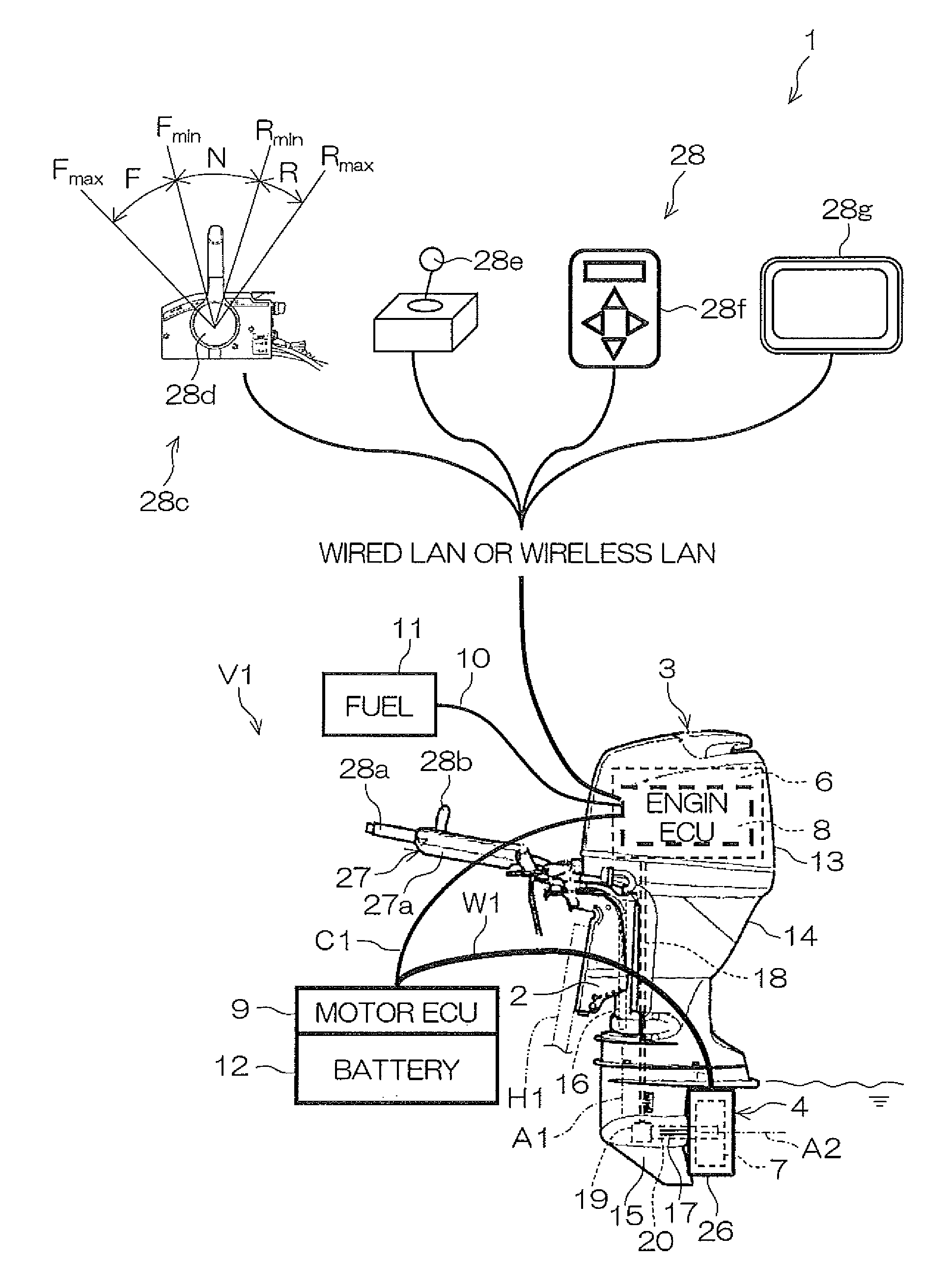
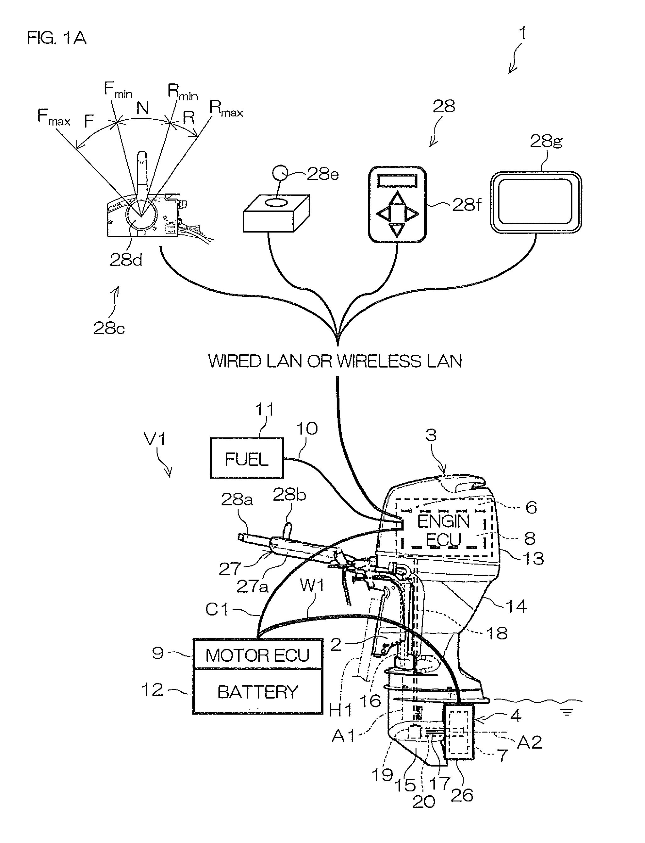
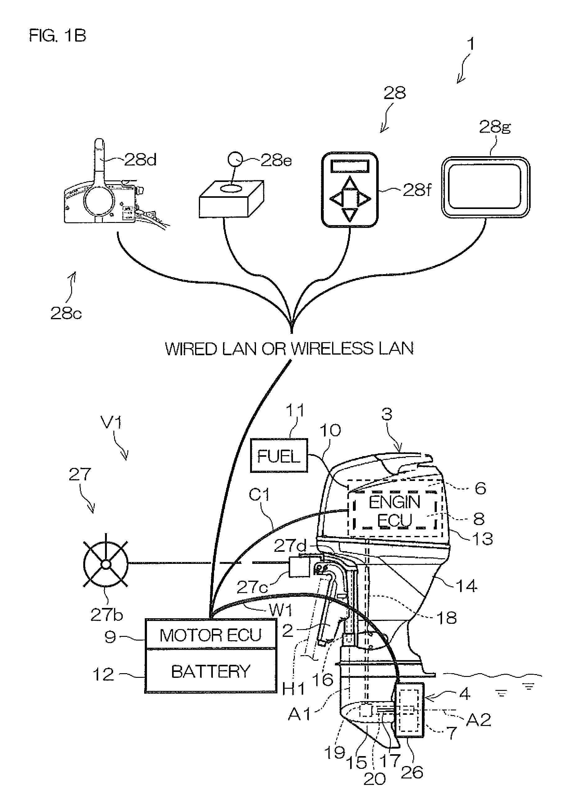
[0085]FIG. 1A and FIG. 1B are side views of a marine vessel propulsion device 1 according to a first preferred embodiment of the present invention. FIG. 2 is a rear view of the marine vessel propulsion device 1 according to the first preferred embodiment of the present invention. FIG. 3 is a schematic view of a forw...


PUM


Abstract

A marine vessel propulsion device includes a propeller rotatable around a propeller axis, a duct that surrounds the propeller around the propeller axis, an internal combustion engine that rotates the propeller relative the duct, and an electric motor that rotates the propeller relative to the duct. The propeller includes a plurality of blades, and a cylindrical rim that surrounds the plurality of blades around the propeller axis. The electric motor rotates the propeller by rotating the rim.

Description

BACKGROUND OF THE INVENTION[0001]1. Field of the Invention[0002]The present invention relates to a marine vessel propulsion device.[0003]2. Description of the Related Art[0004]A hybrid type marine vessel propulsion device including an engine (internal combustion engine) and an electric motor has been disclosed.[0005]For example, United States Patent Application Publication Number US 2008 / 0113569 A1 discloses amarine vessel propulsion device that includes an outboard motor having a built-in engine and a built-in electric motor. The engine is connected to a propeller through a drive shaft, a forward / rearward switching mechanism, and a propeller shaft. The electric motor is placed on the drive shaft between the engine and the forward / rearward switching mechanism. The engine is connected to the electric motor through a multi-plate clutch placed on the drive shaft. When the propeller is driven by the engine, the multi-plate clutch is engaged, and, when the propeller is driven by the elec...

Claims


Application Information

Patent Timeline
Patent Type & Authority Patents(United States)
IPC IPC(8): B63H21/22B63H21/14B63H21/17B63H21/20
CPCB63H21/14B63H21/17B63H21/20B63H2021/205Y02T70/5236B63H1/16B63H20/007B63H2023/005
Inventor SUZUKI, TAKAYOSHIHIRAOKA, NORIYOSHI
Owner YAMAHA MOTOR CO LTD
Why Eureka
Try Eureka