
Elastic rotary actuator

a rotary actuator and elastic technology, applied in the direction of mechanical control devices, instruments, couplings, etc., can solve the problems of unsuitable for this type of control, inability to handle delicate non-modelled objects with precision, and limitations of rotary actuators used today, so as to achieve the effect of higher performan

Inactive Publication Date: 2014-09-02
FOND INST ITAL DI TECH
View PDF10 Cites 27 Cited by
  • Summary
  • Abstract
  • Description
  • Claims
  • Application Information

AI Technical Summary

Benefits of technology

The present invention provides an elastic rotary actuator that has better performance than previous versions. It can store more elastic energy and control the torque it transmits to an external load with greater precision.

Problems solved by technology

In the future, robotics will rely heavily on control algorithms operating in the domain of force and torque control, since this permits applications which cannot be implemented with position control alone.
For example, without an accurate measurement of the forces generated by a robot, it is impossible to handle with precision delicate non-modelled objects or interact with man in safe conditions in an unstructured environment.
The rotary actuators used nowadays have considerable limitations which make them unsuitable for this type of control.
In real systems, it is never possible, even below the control frequency, to eliminate completely the mechanical impedance owing to the frictional forces and the inertial forces due to the non-suspended mass.
Most currently available rotary actuators for robotic applications have a limited force / torque control capacity.
Hydraulic actuators have excellent maximum torque, maximum speed and power / weight ratio characteristics, but very high mechanical impedance.
Therefore it is difficult to use these actuators in actuating systems with torque control.
Pneumatic actuators have an intrinsic compliance because they contain a compressible gas, but they are affected by band control problems owing to the limits of their valves in terms of flow rate and tightness.
Electric actuators are fast, but generally they are able to produce low torques and therefore require the use of reduction units which are subject to high friction and therefore increase considerably mechanical impedance.
Such actuators, however, still suffer from significant performance problems which limit their use in certain applications.

Method used


Image

  • Elastic rotary actuator
  • Elastic rotary actuator
  • Elastic rotary actuator

Examples


Embodiment Construction

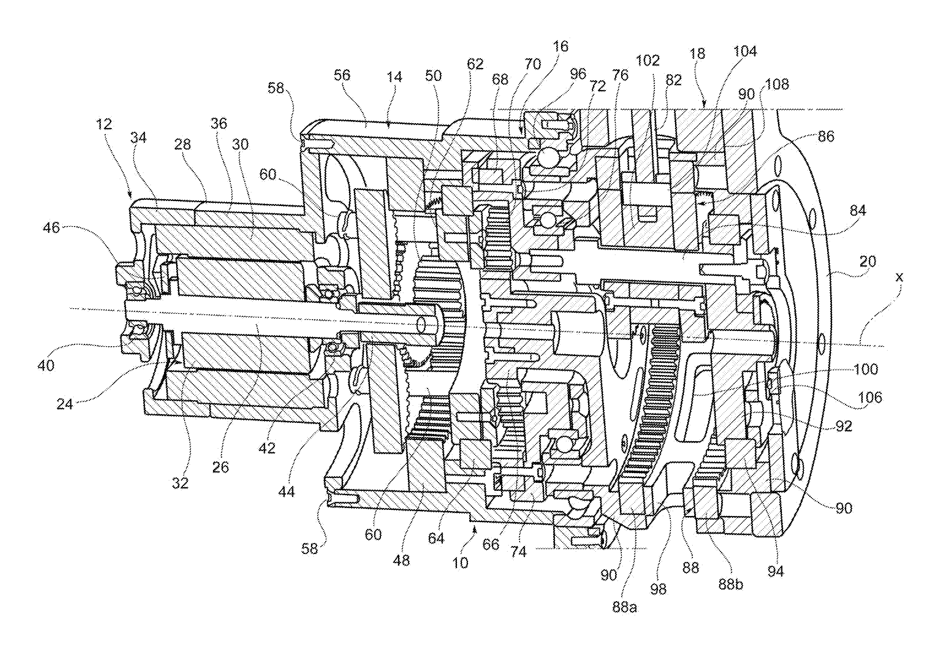
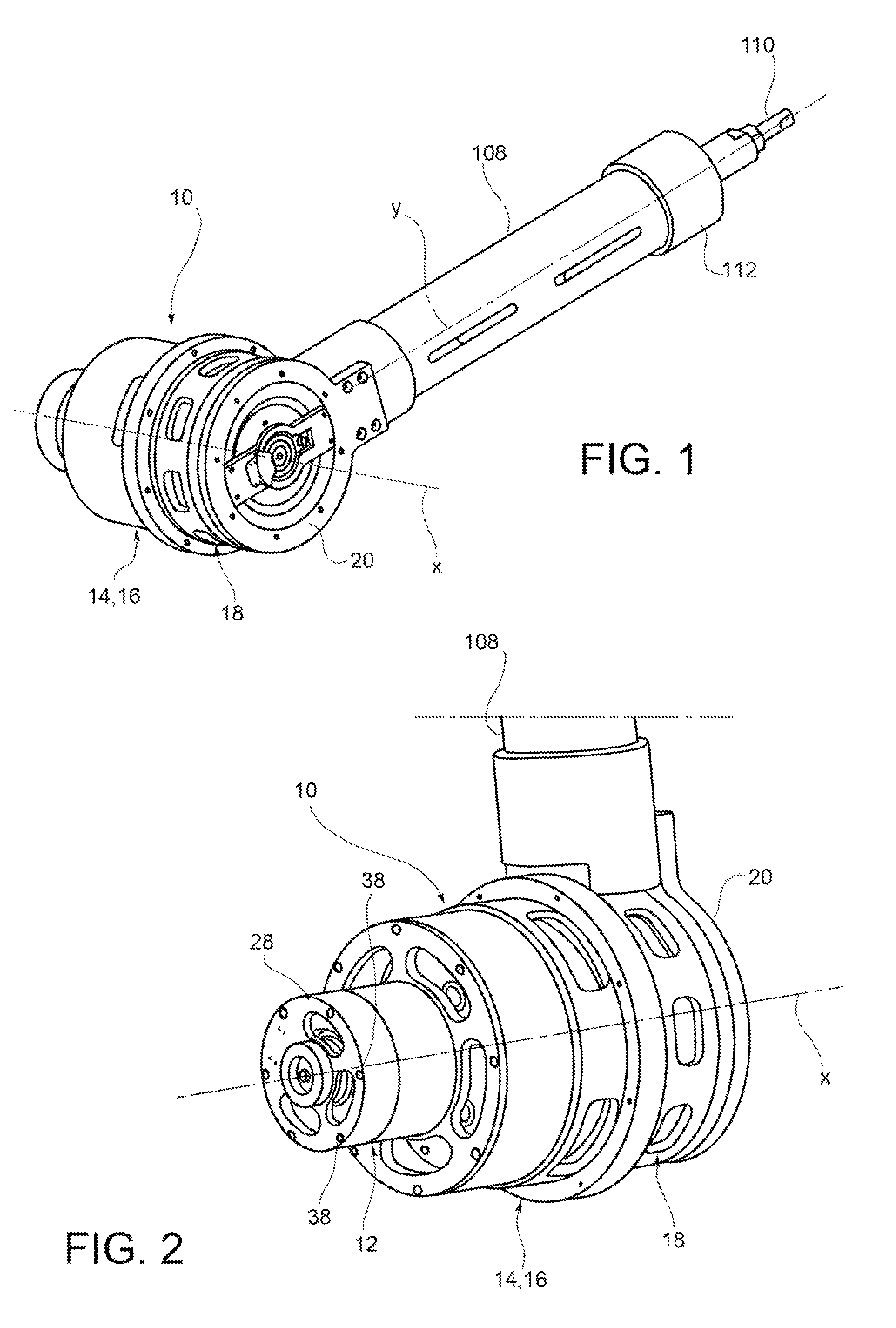
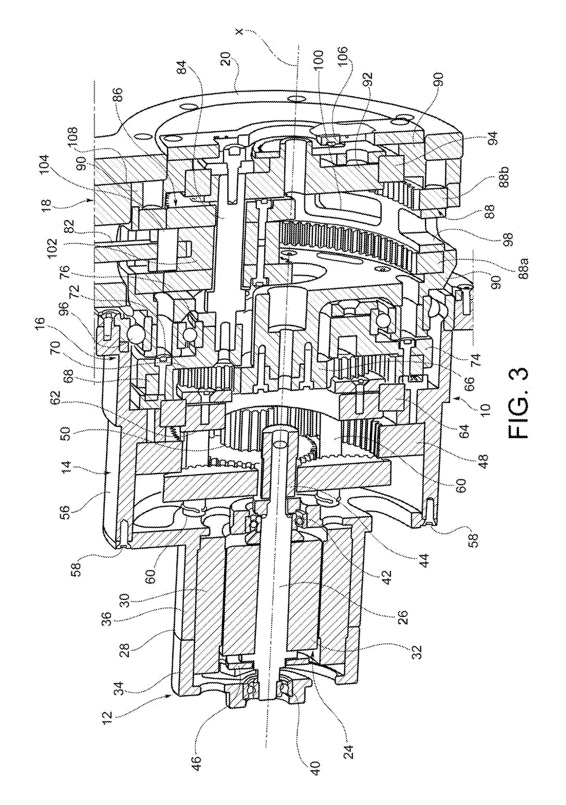
[0029]With reference initially to FIGS. 1 to 3, elastic rotary actuators according to certain embodiments of the present invention are generally indicated 10 and may include a motor unit 12, a reduction unit 14, a differential unit 16, an elastic unit 18 and an final output member 20, the final output member 20 being supported rotatably about an axis of rotation x and being intended to be connected to an external load (not shown), the motor unit 12 being designed to generate a rotary movement about the axis of rotation x, and the reduction unit 14, the differential unit 16 and the elastic unit 18 being arranged axially (where the term “axially”, as well as the term “axial”, are used here to indicate the direction of the axis of rotation x) in that order between the motor unit 12 and the final output member 20 so as to transmit to the final output member 20 the rotary movement generated by the motor unit.

[0030]With reference in particular to FIG. 3, the motor unit 12 may include an e...


PUM


Abstract

Rotary actuators having a final output member rotatable about an axis of rotation; a motor unit designed to drive the final output member for rotation about the axis of rotation; and an elastic unit arranged between the motor unit and the final output member and having an input member torsionally coupled to the motor unit and an output member rigidly connected for rotation with the final output member are provided.

Description

CROSS REFERENCE TO RELATED APPLICATION[0001]This application claims priority to and benefit of Italian Patent Application No. TO2011A000848 filed Sep. 23, 2011, the contents of which are incorporated by reference in their entirety.FIELD OF THE INVENTION[0002]The present invention relates to a rotary actuator, in particular for applications in the robotics sector, where the term “rotary actuator” is to be understood as referring to a device able to produce at its output a rotary movement about an axis of rotation by producing a torque about the axis.BACKGROUND OF THE INVENTION[0003]In the future, robotics will rely heavily on control algorithms operating in the domain of force and torque control, since this permits applications which cannot be implemented with position control alone. For example, without an accurate measurement of the forces generated by a robot, it is impossible to handle with precision delicate non-modelled objects or interact with man in safe conditions in an unst...

Claims


Application Information

Patent Timeline
Patent Type & Authority Patents(United States)
IPC IPC(8): F16H57/08B25J9/04B25J9/08F16D3/50
CPCF16D3/50B25J9/042B25J9/08B25J9/04Y10T74/20305
Inventor THORSON, IVAR
Owner FOND INST ITAL DI TECH
Learn More