Pointing devices, apparatus, systems and methods for high shock environments

a high-shock environment and point device technology, applied in the field of precision pointing, can solve the problems of increasing the gross angular weapon movement, sat housing and mounting components to flex, and the movement and corresponding error is greater, and achieve the effect of accurate linear and angular positioning

Active Publication Date: 2014-09-09
BOWMAN ORVAL E
View PDF55 Cites 5 Cited by
  • Summary
  • Abstract
  • Description
  • Claims
  • Application Information

AI Technical Summary

Benefits of technology

[0020]A primary objective of the present invention is for providing compact devices, apparatus, systems and methods for maintaining accurate linear and angular positioning of a conical shaped cantilevered beam or S shaped cantilevered beam or center deflecting beam with free ends, with each beam having one end with mounted payload, during and after exposure in high G shock and vibration environments, with the capability of adjusting minute changes in beam orientation.
[0021]A secondary objective of the present invention is for providing compact devices, apparatus, systems and methods which maintains the initial precise pointing during and after exposure in high G shock and vibration environments, and does not require joints which have errors.
[0022]A third objective of the present invention is for providing compact devices, apparatus, systems and methods which maintains the initial precise pointing during and after exposure in high G shock and vibration environments, that does not have any static friction (stiction) introduced deflections where the tangential friction forces at the contacting surfaces cause bending deflections of the mechanism's components when boresighted.

Problems solved by technology

For open bolt weapons like the M240 and M249, the movement and corresponding error is greater after the trigger pull due to the time required for the bolt to close and the impact of the bolt increases the gross angular weapon movement.
The shock from the bolt closing and / or the blank firing causes the SAT housing and mounting components to flex and introduce an addition pointing error to the gross weapon movement error which is not repeatable.
Also based on the internal construction, the adjustment mechanism can unload (bounce) during the high G event and introduce additional significant pointing errors which is not repeatable.
The second and third error sources (flexure and unloading) are the problems.
The present SAT design approaches do not maintain the initial precise pointing during and after exposure in high G shock and vibration environments.
For example, U.S. Published Patent Application 2004 / 0005531 to Varshneya et al. describes an elaborate and complex system for calibrating misalignment of a weapon-mounted zeroed small arms transmitter (ZSAT) laser beam axis with the shooter line-of-sight (LOS) in a weapon training system, but fails to easily solve the problem.
Other types of devices have resulted in additional problems.
Some of the proposed devices intentionally shock isolate by allowing movement of the laser beam axis relative to the weapon to prevent damage to the laser or associated electronics and therefore does not maintain alignment during the shock.
There is friction at the sliding and spherical joints due to the preload forces.
This movement will produce a pointing error relative to the initial alignment.
The larger the quality of interfaces, the larger the total pointing error after a shock.
Additional problems with the prior art have included devices having sliding or pivoting joints and geared interfaces that have clearance between the none contacting surfaces can become contaminated which will cause binding or increased friction which will increase the pointing angle error.
Prior art devices have included plural components, threaded rods that translate wedges used for alignment, due to clearances between the mating threaded parts, when the direction and adjustment is reversed, hysteresis will be introduced which is a source of error.
After adjustment, during the shock, the stiction will be relieved and the wedge can move over the range of the thread clearance producing a pointing error.
Some of the prior art devices include large and heavy components for a 1 G or manufacturing environment where there is no shock or vibration environment and there is no limitation on size, weight or adjustment type and are cumbersome for field use, difficult to adjust in the field, or the alignment is set at the factory.
Some of the prior art includes devices which cannot maintain alignment or boresight over the wide temperature operating range from the low −40° C. to the high temperature where the barrel of the M240 can exceed 350° C. Over this temperature range, any mismatch in the components CTE (coefficient of thermal expansion) will cause binding or increased clearances at the interfaces which will increase the pointing errors.
The component's CTE mismatch will also introduce a bimetallic error as the temperature changes from the initial adjustment temperature.
Still other prior art devices use different types of springs to preload the system against the adjustment stops so a payload does not move away from the stop and produce a dynamic pointing error.
The springs used cannot produce enough force in the limited volume to counteract the unloading force.

Method used


Image

  • Pointing devices, apparatus, systems and methods for high shock environments
  • Pointing devices, apparatus, systems and methods for high shock environments
  • Pointing devices, apparatus, systems and methods for high shock environments

Examples


Embodiment Construction

[0071]Before explaining the disclosed embodiments of the present invention in detail it is to be understood that the invention is not limited in its applications to the details of the particular arrangements shown since the invention is capable of other embodiments. Also, the terminology used herein is for the purpose of description and not of limitation.

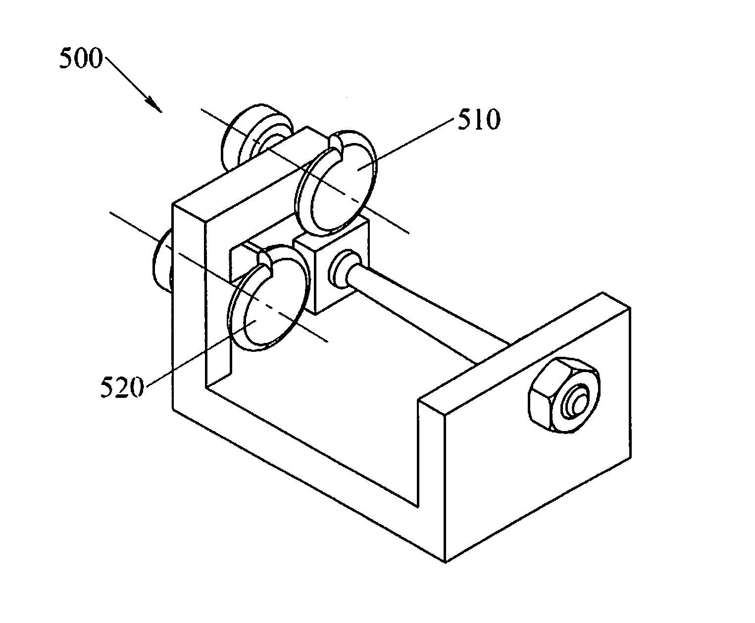
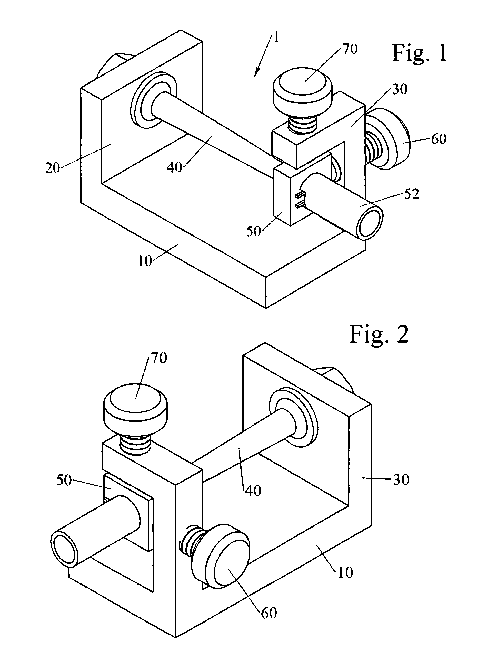
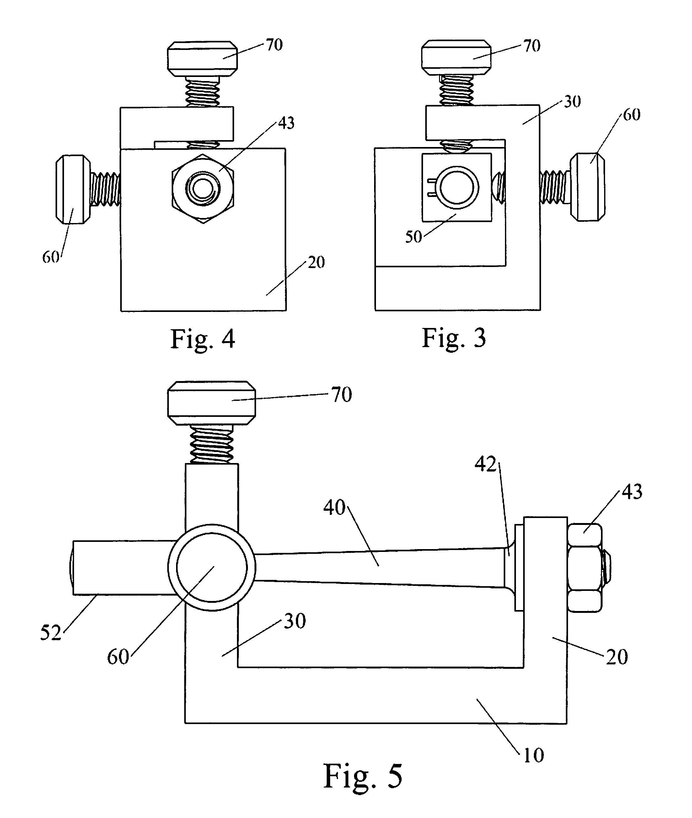
[0072]A listing of components will now be described.[0073]1. laser system with conical cantilevered beam[0074]10. base of housing[0075]20. rear wall of housing[0076]25. threaded opening for battery[0077]30. support housing portions for adjustment controls[0078]32. front top of housing[0079]33. cover of housing[0080]34. front side of housing[0081]38. front wall of housing[0082]39. cover mounting screws / washer[0083]40. cantilevered conical beam[0084]42. base wide end[0085]43. fastener (nut)[0086]48. narrow tip end[0087]50. payload[0088]52. laser housing[0089]53. laser diode[0090]56. lens[0091]60. lateral adjustment control[0092]61. o-...


PUM


Abstract

Devices, apparatus, systems and methods for providing accurate linear and angular positioning with a payload mounted to a conical shaped cantilevered supported beam or S shaped cantilevered beam or a center deflecting beam having freely moveable ends. The payload can be a laser pointer mounted on a firearm, which maintains the initial precise pointing during and after exposure in high G shock and vibration environments. Vertical and lateral adjustment controls can adjust minute changes in beam orientation. Precision adjustments can be performed in a zero G, one G, or high G environment and maintains the adjustment during and after being exposed to a high G shock or vibration environment.

Description

CROSS REFERENCE TO RELATED APPLICATIONS[0001]This invention claims the benefit of priority to U.S. Provisional Application 61 / 629,737 filed Nov. 26, 2011.FIELD OF INVENTION[0002]This invention relates to precision pointing, in particular to devices, apparatus, systems and methods for providing accurate linear and angular positioning of a payload, such as a laser pointer and maintains the initial precise pointing during and after exposure in high G shock and vibration environments, with the capability of adjusting minute changes in beam orientation, where the beam supporting the payload can be a cantilevered conical shaped beam or cantilevered S shaped beam or a center deflecting beam with freely movable ends. The precision adjustments can be performed in a zero G, one G, or high G environment and maintains the adjustment during and after being exposed to a high G shock or vibration environment.BACKGROUND AND PRIOR ART[0003]Laser pointing devices have been widely used on firearms to ...

Claims


Application Information

Patent Timeline
Patent Type & Authority Patents(United States)
IPC IPC(8): F41G1/36F41G1/00H01S5/0231F41G1/35H01S3/02H01S5/0239
CPCF41G1/36F41G1/00F41G1/35H01S3/025H01S5/02244F41G1/34F41G1/545H01S5/022H01S5/0239H01S5/0231F41G1/393
Inventor BOWMAN, ORVAL, E.
Owner BOWMAN ORVAL E
Why Eureka
Try Eureka