Vehicle package tray

a technology for storing containers and trays, which is applied in the direction of roofs, transportation and packaging, synthetic resin layered products, etc., can solve the problems of increasing the weight of the container, not substantially having a sound absorption performance, and heavy weight of the container

Active Publication Date: 2014-09-09
HOWA MASCH LTD
View PDF9 Cites 4 Cited by
  • Summary
  • Abstract
  • Description
  • Claims
  • Application Information

AI Technical Summary

Benefits of technology

[0009]With the above configuration, the vehicle package tray is configured to include the semi-hard urethane foam layer. Here, a configuration including the semi-hard urethane foam layer is employed in view of a problem that the strength lacks in the case of a configuration including a soft urethane foam layer and a hard urethane foam layer is not easily formed into a three-dimensional shape. Furthermore, the sheet-shaped fiber-reinforced materials, in which the thermal hardening resin is impregnated, are overlapped on both surfaces of the semi-hard urethane foam layer. Although this can be considered to be because the strength lacks in the configuration including only the semi-hard urethane foam layer, it is possible to achieve desired rigidity for the vehicle package tray by the laminated configuration of the fiber-reinforced materials which also provides rigidity in addition to the configuration of the semi-hard urethane foam layer. In addition, the laminated structure of the semi-hard urethane foam layer and the fiber-reinforced materials makes it possible to thin the plate thickness as compared with the configuration which includes only a hard urethane foam layer and to reduce weight. In addition, the configuration of the semi-hard urethane foam layer can provide a vehicle package tray with a sound absorbing performance. Moreover, the front surface material and the back material which are configured on the outer surfaces of the semi-hard urethane foam layer and the fiber-reinforced material are also overlapped, pinched and fixed by the press die, and heated and pressurized. Therefore, it is possible to obtain inexpensive vehicle package tray by a smaller number of processes. In addition, the semi-hard urethane foam layer makes it easier to form three-dimensional shape by press molding. As described above, it is possible to provide a vehicle package tray which has rigidity for allowing placement of an article thereon and assembly of vehicle accessories therein and further has a sound absorbing performance.
[0011]With the above configuration, it is possible to block airflow between a trunk space and a vehicle interior space and suppress adhesion of so-called airflow contamination to the surface of the front surface material. In addition, the airflow blocking layer also provides a sound blocking performance. For example, when the airflow blocking layer is provided on the side of the first adhesive film on which the front surface material is overlapped, the sound blocking performance is exhibited between the front surface material and the fiber-reinforced material. Thus, since the semi-hard urethane foam layer is provided at a position closer to the side of the back material than the airflow blocking layer, the vehicle package tray which absorbs sound on the side of the trunk when mounted on the vehicle is obtained. On the other hand, when the airflow blocking layer is provided on the side of the second adhesive film on which the back material is overlapped, the sound blocking performance is exhibited between the back material and the fiber-reinforced material. Thus, since the semi-hard urethane foam layer is provided at a position closer to the front surface material than the airflow blocking layer, the vehicle package tray which absorbs sound on the side of the vehicle interior when mounted on the vehicle is obtained. That is, it is possible to select which one side out of the vehicle interior side or the trunk side the sound absorbing performance is to be provided depending on a laminated position of the airflow blocking layer.
[0013]With the above configuration, it is possible to provide the sound blocking performance, and also facilitate adhesion of the front surface and the back material to the fiber-reinforced materials.
[0015]With the above configuration, the semi-hard urethane foam layer has the CS hardness from 30 to 55, the density from 0.025 g / cm3 to 0.035 g / cm3, the cell diameter from 0.2 mm to 0.5 mm, and the open-cell rate of not less than 90%. It is possible to preferably employ the semi-hard urethane foam layer with the above configuration from an aspect that the vehicle package tray has both the sound absorbing performance and the strength.
[0017]With the above configuration, the thickness of the semi-hard urethane foam layer ranges from 2.0 mm to 10.0 mm before molding by heating and pressurizing. Thus, it is possible to preferably employ the thickness of the semi-hard urethane foam layer with the above configuration from aspects of the sound absorbing performance, the strength, and further the weight of the vehicle package tray.

Problems solved by technology

However, both the vehicle package trays as the injection-molded article and as a fiber-reinforced plastic article have a problem that the weights thereof are heavy despite having rigidity.
In addition, these vehicle package trays have a sound blocking performance for blocking noise from the trunk and do not substantially have a sound absorbing performance.
Therefore, a sound absorbing material is attached to the surface of the vehicle package tray on the side of the trunk in order to add the sound absorbing performance, which results in a further increase in the weight, and there is a concern that manufacturing cost increases.
In addition, there is a problem that it is difficult to perform an operation for embedding the vehicle accessories such as the speaker and the stop lamp (JP-A-7-89395, for example).
In addition, there is also a concern that the weight of the vehicle package tray with the increased plate thickness becomes heavy as a result.
In addition, there is a concern that it becomes difficult to perform molding into a three-dimensional shape when molding in a state where the plate thickness of the hard urethane foam layer is increased.
Moreover, there is a concern that so-called airflow contamination remarkably appears on the surface of the front surface material due to airflow between the trunk space and the vehicle interior space only by the configuration in which the front surface material is attached to the hard urethane foam layer.
Therefore, there is a concern that noise from the outside of the vehicle enters the vehicle interior through the glass.

Method used


Image

  • Vehicle package tray
  • Vehicle package tray
  • Vehicle package tray

Examples


example 1

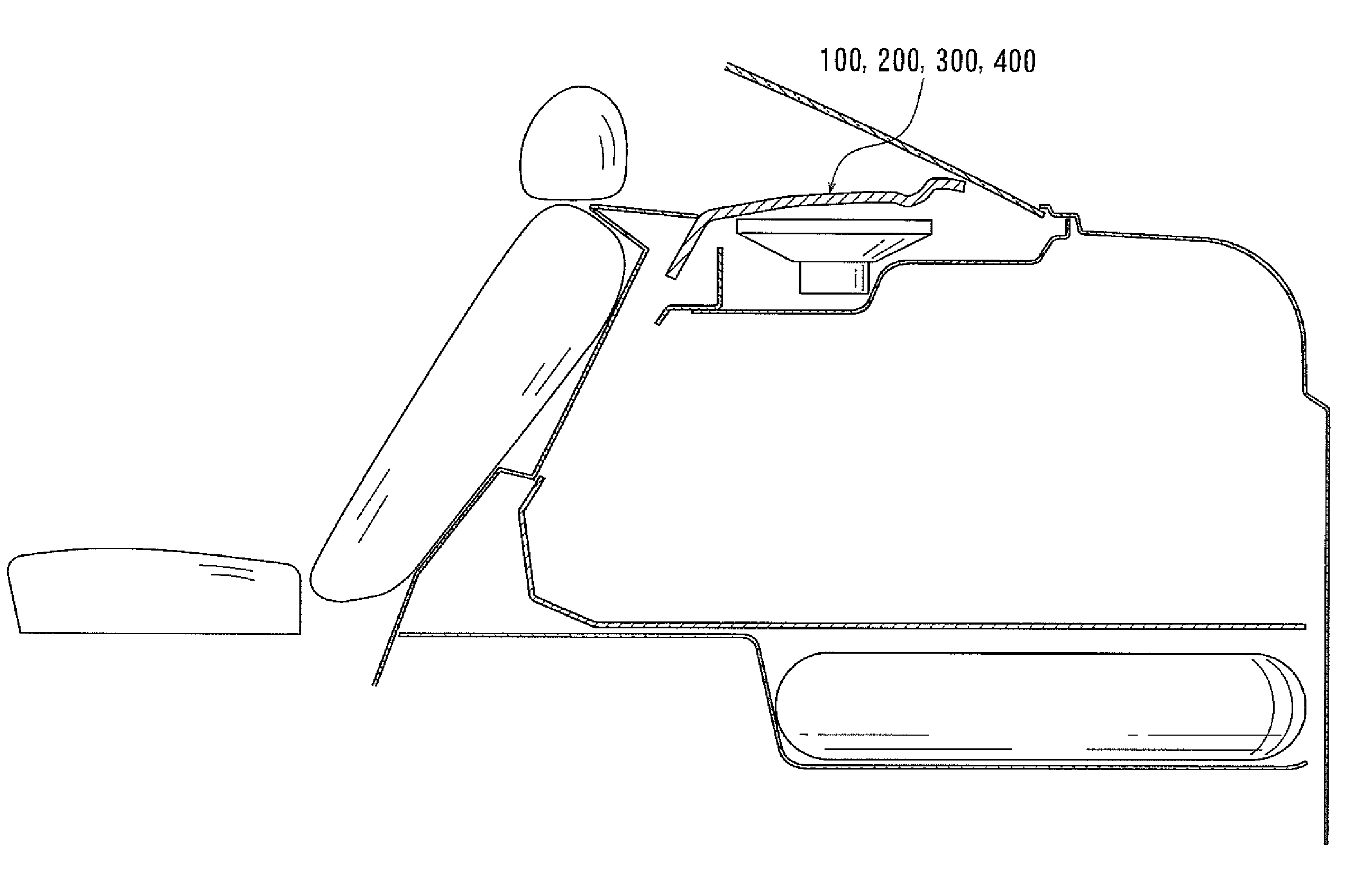
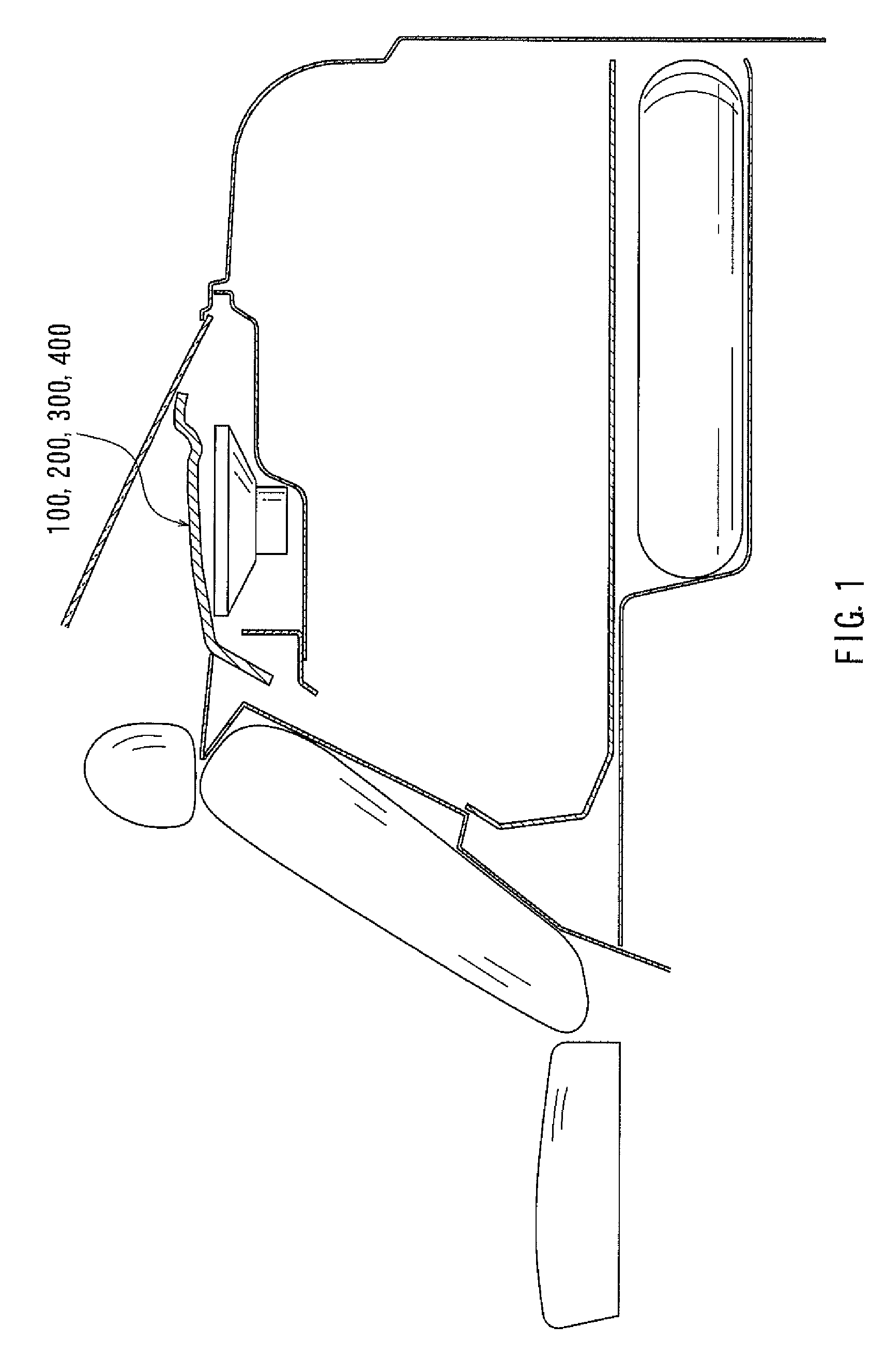
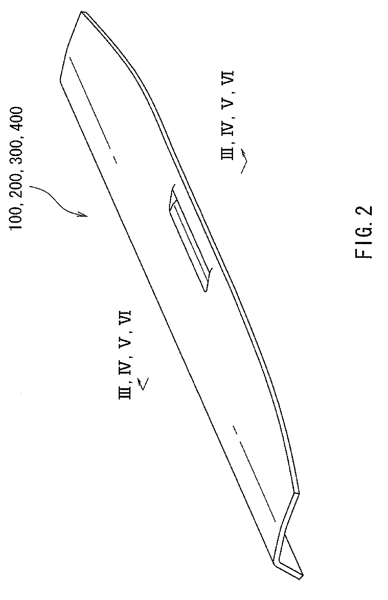
[0062]FIG. 1 shows a vehicle to which a vehicle package tray 100 according to this example is applied. FIG. 2 is an entire perspective view showing the vehicle package tray 100 according to the example of the present disclosure, and FIG. 3 is a partially enlarged cross-sectional view of the vehicle package tray 100 according to the example of the present disclosure.

[0063]As shown in FIG. 3, a configuration of a vehicle package tray 100 according to Example 1 is formed into a three-dimensional shape by pinching and fixing by a press die a laminated body including a front surface material 104, a first adhesive film 106, a glass fiber mat 108, urethane resin 110, a semi-hard urethane foam layer 102, urethane resin 110, a glass fiber mat 108, a second adhesive film 112, and a back material 114, heating and pressurizing the laminated body, and thereby fusing the laminated body. Here, the semi-hard urethane foam layer 102 of the vehicle package tray 100 in Example 1 has respective propert...

example 2

[0068]Next, a description will be given of Example 2. As shown in FIG. 4, a configuration of a vehicle package tray 200 according to Example 2 is formed into a three-dimensional shape by pinching and fixing by a press die a laminated body including the front surface material 104, the first adhesive film 106, a glass fiber mat 108a, urethane resin 110a, a semi-hard urethane foam layer 102a, urethane resin 110a, a glass fiber mat 108a, the second adhesive film 112, and the back material 114, heating and pressurizing the laminated body to fuse the laminated body.

[0069]Although the semi-hard urethane foam layer 102a of the vehicle package tray 200 in Example 2 is configured by the same material as that in Example 1, the thickness of 5.5 mm is selected. The front surface material 104 has the same configuration as that in Example 1. The first adhesive film 106 has the same configuration as that in Example 1. In addition, the sheet-shaped glass fiber mat 108a with a unit weight of 200 g / m2...

example 3

[0073]Next, a description will be given of Example 3. As shown in FIG. 5, a configuration of a vehicle package tray 300 according to Example 3 is formed into a three-dimensional shape by pinching and fixing by a press die, a laminated body including the front surface material 104, the first adhesive film 106, a glass fiber mat 108b, urethane resin 110b, a semi-hard urethane foam layer 102b, urethane resin 110b, a glass fiber mat 108b, the second adhesive film 112, and the back material 114, and heating and pressurizing the laminated body to fuse the laminated body.

[0074]Although the semi-hard urethane foam layer 102b of the vehicle package tray 300 in Example 3 is configured by the same material as that in Example 1, the thickness of 4.0 mm is selected. The front surface material 104 has the same configuration as that in Example 1. The first adhesive film 106 has the same configuration as that in Example 1. In addition, the sheet-shaped glass fiber mat 108b with a unit weight of 135...


PUM

PropertyMeasurementUnit
cell diameteraaaaaaaaaa
densityaaaaaaaaaa
thicknessaaaaaaaaaa

Abstract

In a vehicle package tray (100) disposed in the back of a rear seat of a vehicle, a sheet-shaped glass fiber mats (108), in which urethane resin (110) is impregnated, are overlapped on both surfaces of a semi-hard urethane foam layer (102), a front surface material (104) is overlapped on the surface of one glass fiber mat (108), in which the urethane resin (110) is impregnated, via a first adhesive film (106), back material (114) is overlapped on the surface of the other glass fiber mat (108), in which the urethane resin (110) is impregnated, via a second adhesive film (112), and the multi-overlapped object obtains a sound absorbing performance by being formed into a three-dimensional shape by being pinched and fixed by a press die, heated, pressurized, and thereby fused.

Description

TECHNICAL FIELD[0001]The present invention relates to a vehicle package tray.BACKGROUND ART[0002]In recent years, a vehicle interior has been required to be more silent, and various kinds of means for suppressing wind noise from outside the vehicle, noise from tires, and the like coming inside the vehicle interior have been proposed. For example, a vehicle package tray, which is disposed on a back side of a rear seat in a vehicle, has been known. The vehicle package tray is one of interior parts in a vehicle, serves as a design for improving an appearance of the vehicle interior, and also functions as a place where an object is placed, or where vehicle accessories such as a speaker and a stop lamp are embedded. Furthermore, the vehicle package tray is configured as a wall which sections a trunk space and a vehicle interior space and thereby prevents noise from the outside of the vehicle interior from entering from the trunk space to the vehicle interior space.[0003]Here, the vehicle...

Claims


Application Information

Patent Timeline
Patent Type & Authority Patents(United States)
IPC IPC(8): B60R7/04B60R5/04B60R13/08
CPCB60R13/08B60R5/044B32B5/022B32B5/026B32B5/18B32B7/12B32B27/065B32B27/12B32B27/32B32B27/40B32B2260/021B32B2260/046B32B2262/101B32B2266/0278B32B2307/102B32B2307/718B32B2307/72B32B2605/00
Inventor KURODA, ATSUSHISETO, HIROYUKI
Owner HOWA MASCH LTD
Why Eureka
Try Eureka