
Apparatus for alternately sifting and blending powders in the same operation

a technology of powder sifting and blending, which is applied in the field of powder processing, can solve the problems of time-consuming multiple handling process, insufficient amount of active ingredients, and inability to yield uniform powders, etc., and achieves the effect of efficient sifting and blending powders thoroughly, improved mixing, and convenient mounting

Active Publication Date: 2014-09-09
KALIDINDI SANYASI R
View PDF26 Cites 19 Cited by
  • Summary
  • Abstract
  • Description
  • Claims
  • Application Information

AI Technical Summary

Benefits of technology

The present invention is an improved apparatus for sifting and blending powders in a single operation. It includes an arcuate screen and a paddle agitator for efficient mixing. The screen and agitator are each made of multiple sections, making them easier to mount, assemble, and replace. This design also allows for improved mixing, especially in large blenders, and reduces the risk of operator injury. It simplifies maintenance and cleaning. Overall, this apparatus provides a more efficient and cost-effective solution for blending powders.

Problems solved by technology

Unless the mixing is thorough, parts of the production batch will have an insufficient amount of active ingredient to be effective, and parts of the production batch will have an excess amount of active ingredient and could be detrimental.
However, even blending of a micronized active ingredient with other ingredients in a tumbling blender with an intensifier bar does not always yield a uniform blend.
This multiple handling process is time consuming and generates dust from the powder ingredients.
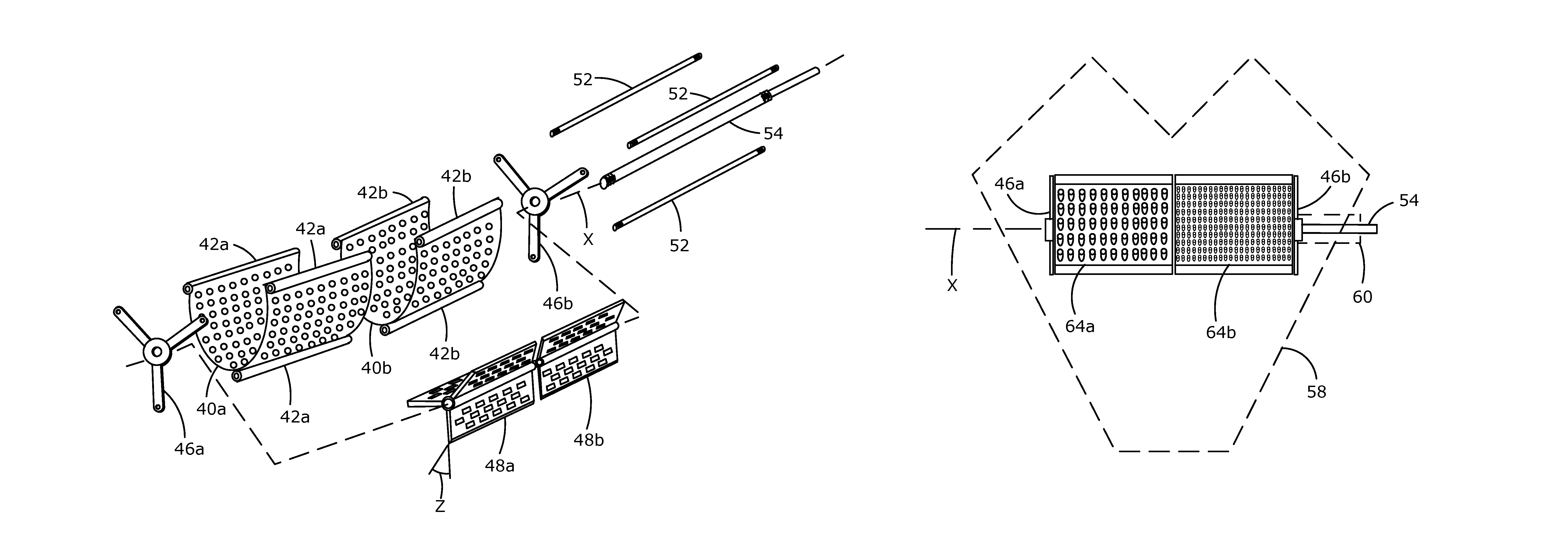
Whereas the '582 patent teaches a useful and unique method, it has been determined that in large equipment for sifting and blending powders, e.g. typically on the order of 150 kg to 2000 kg powder capacity, it is difficult or impossible to install and remove a single piece screen and single piece paddle as described above through the cover openings in the tumbling container.

Method used


Image

  • Apparatus for alternately sifting and blending powders in the same operation
  • Apparatus for alternately sifting and blending powders in the same operation
  • Apparatus for alternately sifting and blending powders in the same operation

Examples


Embodiment Construction

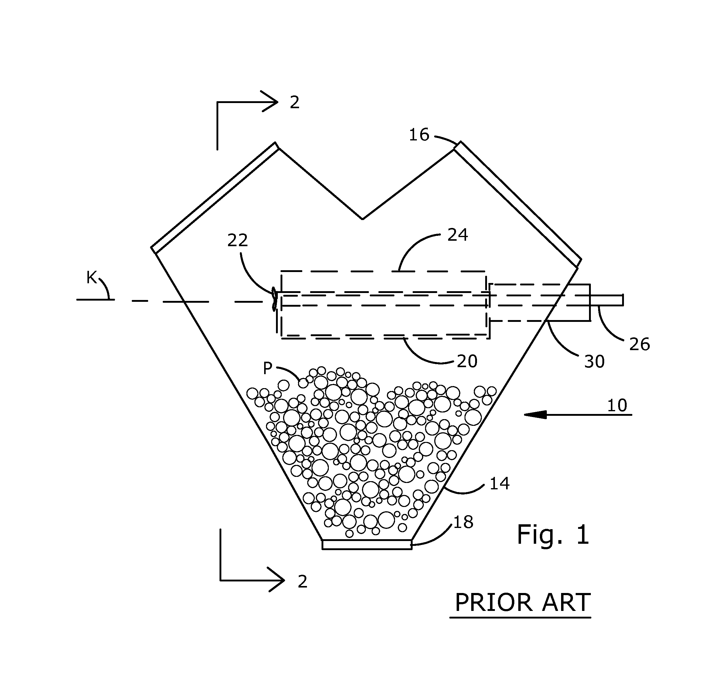
[0016]Referring to FIG. 1, an apparatus 10 used for sifting and blending powders is shown in front elevation. A tumbler 14, e.g. a V-blender, is shown in upright orientation. V-blenders, as are known, are effective by dividing and re-combining the powders as the blender rotates end over end. While the preferred embodiment of the invention incorporates a V-blender, the principles disclosed herein are deemed to pertain to various tumbling blender geometries. Tumbler 14 is mounted for rotation around axis K. A pair of top closures 16 and a bottom closure 18 are mounted to the top and bottom respectively of tumbler 14 to contain ingredients therein. A trunnion 30 is fixedly mounted to the wall of tumbler 14 to be concentric with axis K with a portion of trunnion 30 extending into the free space within tumbler 14. A semi-tubular screen 20 is fixedly mounted to trunnion 30 by means of a plurality of fasteners 22, e.g. long shafted screws. A drive shaft 26 which passes through a bore throu...


PUM

PropertyMeasurementUnit
radial lengthaaaaaaaaaa
axis of curvatureaaaaaaaaaa
speedsaaaaaaaaaa

Abstract

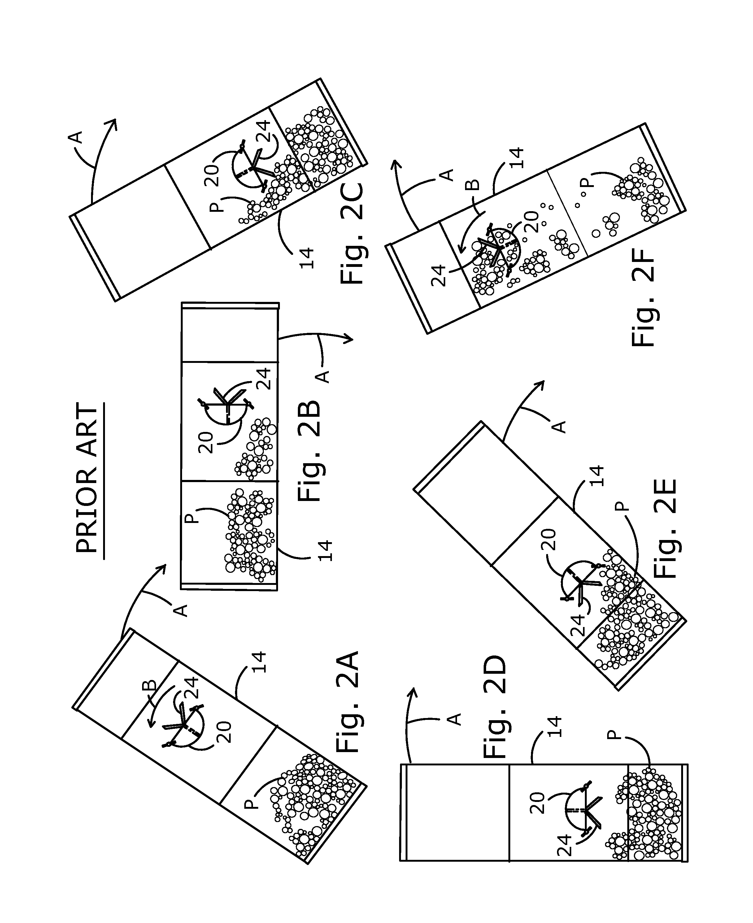
A tumbling container is mounted for rotation with a curved screen fixedly mounted within the tumbling container. A multiple vane paddle is mounted to a shaft that is rotatably mounted to the tumbling container. The paddle vanes are formed with angular edges. As the tumbler rotates and the paddle rotates, powder is repeatedly dropped onto the screen to be sifted with the aid of the paddle. Rotating the tumbler further drops unsifted portions of the powder from the screen to mix with additional powder in the tumbler body. Thus, sifting and blending of powders is accomplished in one single operation. The invention utilizes an apparatus having a multiple section screen and a multiple section paddle to enable assembly through the openings in the tumbling container. The screen of a second embodiment has a cowl adjacent to each screen opening to optimize powder lump disintegration.

Description

FIELD OF THE INVENTION[0001]The present invention relates to the field of powder processing, and more particularly to an apparatus for alternately sifting and blending a mix of powders in the same operation.BACKGROUND OF THE INVENTION[0002]Many pharmaceutical products are made by blending several powders in production quantities. Careful control is essential to ensure uniformity within a given batch and from one batch to another. A typical pharmaceutical may involve five or more ingredients in powder form. It is not uncommon for one or more of the powder ingredients to contain lumps, i.e. a quantity of the powder stuck together, that must be disintegrated to enable uniform blending with other ingredients. Often there is only one active ingredient that comprises a very small fraction of the total ingredients to be combined, typically measured in micrograms or milligrams. Unless the mixing is thorough, parts of the production batch will have an insufficient amount of active ingredient...

Claims


Application Information

Patent Timeline
Patent Type & Authority Patents(United States)
IPC IPC(8): B01F9/08B01F29/60B01F29/62B01F29/64B01F29/83
CPCB01F13/1041B01F15/00928B01F9/005B01F9/08B07B1/24B01F15/00935B01F9/04B01F3/18B01F2013/108B01F23/60B01F29/40118B01F29/62B01F29/64B01F33/83B01F33/83611B01F35/56B01F35/561
Inventor KALIDINDI, SANYASI, R.
Owner KALIDINDI SANYASI R
Learn More