Monocentric lens-based multi-scale optical systems and methods of use

a monocentric lens and optical system technology, applied in the field of optics, can solve the problems the angular resolution and the number of resolvable object points typically scale, and the optical performance of such camera systems begins to suffer, so as to reduce the magnitude of chromatic and spherical aberration correction, and reduce the magnitude of field curvature

Active Publication Date: 2014-09-09
DUKE UNIV
View PDF37 Cites 30 Cited by
  • Summary
  • Abstract
  • Description
  • Claims
  • Application Information

AI Technical Summary

Benefits of technology

[0013]In an optical system in accordance with the present invention, an objective lens collects light from a scene and images the light at a substantially spherically shaped image field. A substantially spherically shaped arrangement of secondary lenses is located near, but displaced from, the image field. Each secondary lens processes light received from the objective lens and images it onto a corresponding sensor array, which converts the imaged light into a digital representation of a portion of the scene. The substantially spherically shape of the arrangement of secondary lenses affords embodiments of the present invention the ability to mitigate the effects of field curvature in the output of the objective lens.
[0014]An objective lens in accordance with the present invention is characterized by a layered structure that includes a spherical central lens element and one or more spherically shaped lens shells, wherein all surfaces have a common center of curvature. The lens shells are designed so that refraction at interior surface of the objective lens produces negative spherical aberration that offsets the positive spherical aberration introduced at the entry surface of the objective lens. The spherically shaped lens shells further enable a reduction in the magnitude of each of chromatic and spherical aberrations in the output of the lens. This reduces the magnitude of chromatic and spherical aberration correction required by the secondary lenses in order to achieve a high-quality image of the scene at the sensor arrays. As a result, the prescription of each secondary lens can be less severe, which, in turn, reduces the amount of coma and astigmatism introduced by the secondary lenses into their respective image fields. In addition, simpler secondary lenses enable a smaller overall optical system volume. Further, a simpler prescription enables secondary lenses that are easier and cheaper to manufacture.
[0016]An illustrative embodiment of the present invention comprises a monocentric objective lens, a plurality of secondary lenses, and plurality of sensors. The monocentric lens includes a substantially spherical central element and a plurality of spherically shaped shell elements, wherein the central element and shell elements are concentric. The central element comprises calcium fluoride, which provides a positive focusing power for the lens. In addition, calcium fluoride is characterized by low chromatic dispersion, which facilitates correction of chromatic aberration. Each of the shell elements comprises a glass having an Abbe number that is lower than the Abbe number of the central element. The inclusion of the shell elements in the objective lens enables a reduction in the magnitude of both chromatic and spherical aberrations in the output of the lens. In some embodiments, an air gap is included between two of the shell elements, which facilitates simultaneous correction of chromatic and spherical aberration without introducing significant dispersion.
[0017]In some embodiments, each secondary lens is paired with a different sensor array to collectively define one of a plurality of substantially identical sub-imaging units. The sub-imaging units collectively provide a composite digital representation of the scene. In some embodiments, the sub-imaging units are arranged such that each image point is received by at least two secondary lenses so that the plurality of secondary lenses collectively provides an image of the scene that is substantially free of blind spots.

Problems solved by technology

Unfortunately, angular resolution and number of resolvable object points typically scale with the size of an imaging system.
As a result, the optical performance of such camera systems begins to suffer as the optical elements and detector elements continue to shrink.
The result is reduced system volume; however, the reduction in system volume is achieved at the cost of significant computational post-processing and compromised image quality.
In addition, the design space for multi-aperture cameras is severely restricted, which has limited their adoption in practical systems.
As a result, conventional multi-aperture designs are generally restricted to very small collection apertures.
This also limits the number of camera formats that can be designed.
Further, a multi-aperture camera typically has a restricted field-of-view due to a need to prevent the overlapping of sub-images on the detector array.
Alternatively, absorbing barriers can be placed between the sub-image regions of the detector array; however, this significantly increases manufacturing cost and complexity.

Method used


Image

  • Monocentric lens-based multi-scale optical systems and methods of use
  • Monocentric lens-based multi-scale optical systems and methods of use
  • Monocentric lens-based multi-scale optical systems and methods of use

Examples


Embodiment Construction

[0036]The following terms are defined for use in this Specification, including the appended claims:[0037]Spherical is defined being characterized by (1) a common center of curvature and (2) a uniform radius of curvature. A spherical surface, for example, is a surface that has substantially the same shape as at least a portion of a sphere.[0038]Apochromatic is defined as focusing three or more wavelengths at substantially the same focal distance or image field.

[0039]This invention is a continuation-in-part of parent case U.S. patent application Ser. No. 12 / 651,894 filed 4 Jan. 2010, entitled “Multi-scale Optical System.”

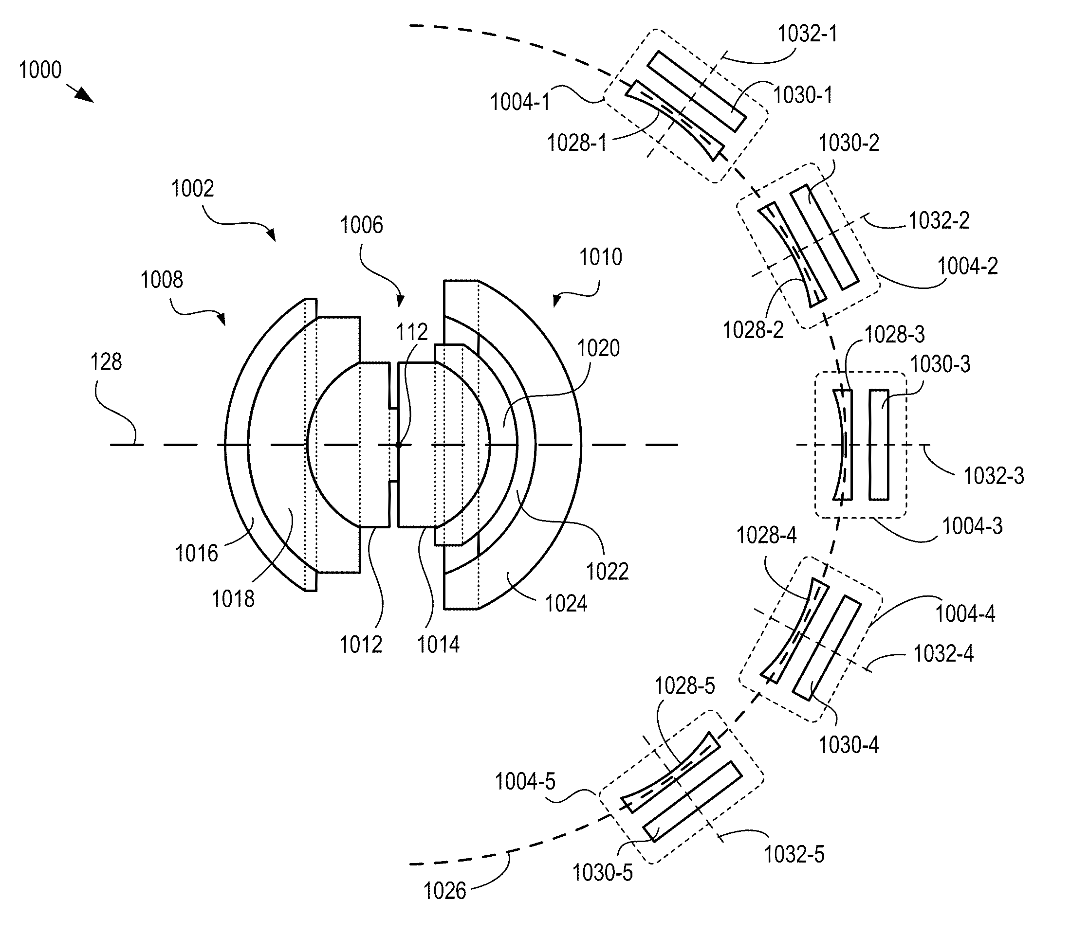
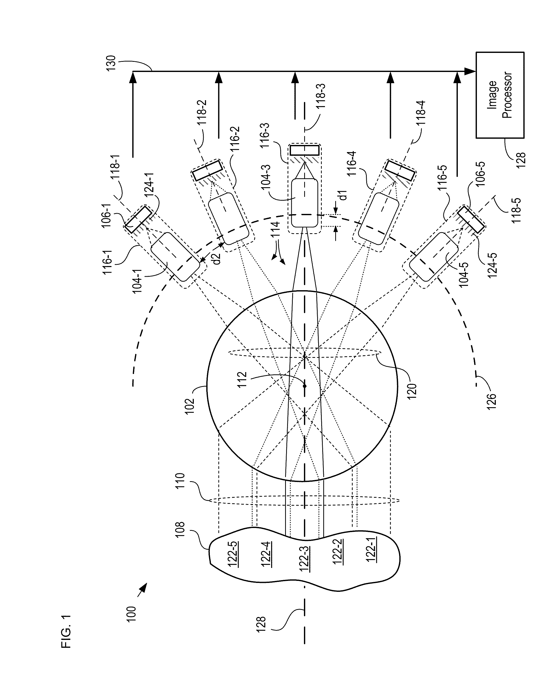
[0040]As disclosed in the parent case, a multi-scale optical system comprises a single objective lens and an array of small secondary lenses. The objective lens and the secondary lenses collectively image a scene onto a plurality of sensor arrays, such as photodetector arrays, as a plurality of optical sub-images. Each secondary lens has a unique optical axis and imag...


PUM


Abstract

A monocentric lens-based multi-scale imaging system is disclosed. Embodiments of the present invention comprise a monocentric lens as an objective lens that collects light from a scene. Monocentric lenses in accordance with the present invention include a spherical central lens element and a plurality of lens shell sections that collectively reduce at least one of spherical and chromatic aberration from the magnitude introduced by the spherical lens element itself. A plurality of secondary lenses image the scene through the objective lens and further reduce the magnitude of aberrations introduced by the objective lens. A plurality of sensor arrays converts optical sub-images of the scene into a plurality of digital images, which can then be used to form a composite image of the scene.

Description

CROSS REFERENCE TO RELATED APPLICATIONS[0001]This case is a continuation-in-part of co-pending U.S. patent application Ser. No. 12 / 651,894 filed 4 Jan. 2010, which is incorporated herein by reference in its entirety.[0002]This application also claims the benefit of U.S. Provisional Patent Application Ser. No. 61 / 328,213, filed Apr. 27, 2010, entitled “Monocentric Lenses for Multi-scale Optical Systems and Methods of Use,” which is incorporated herein by reference in its entirety.FIELD OF THE INVENTION[0003]The present invention relates to optics in general, and, more particularly, to imaging systems.BACKGROUND OF THE INVENTION[0004]A digital camera system is normally based on a lens system comprising a number of optical elements that image a scene onto an array of optoelectronic detector elements. As digital camera systems have evolved, these optical elements and detector arrays have been becoming progressively smaller. Unfortunately, angular resolution and number of resolvable obje...

Claims


Application Information

Patent Timeline
Patent Type & Authority Patents(United States)
IPC IPC(8): H04N5/225G02B13/06G02B27/00H04N5/262
CPCG02B13/06H04N5/2254H04N5/2624G02B27/0025H04N5/247G02B13/006H04N5/37213H04N23/55H04N23/45H04N23/90H04N25/713G02B3/00G02B13/0095G02B2003/0093G06T5/50G06T2207/10016H04N5/265
Inventor MARKS, DANIELBRADY, DAVID JONES
Owner DUKE UNIV
Why Eureka
Try Eureka