Monocentric Lens-based Multi-scale Optical Systems and Methods of Use

Active Publication Date: 2011-09-01
DUKE UNIV
View PDF27 Cites 64 Cited by
  • Summary
  • Abstract
  • Description
  • Claims
  • Application Information

AI Technical Summary

Benefits of technology

[0013]In an optical system in accordance with the present invention, an objective lens collects light from a scene and images the light at a substantially spherically shaped image field. A substantially spherically shaped arrangement of secondary lenses is located near, but displaced from, the image field. Each secondary lens processes light received from the objective lens and images it onto a corresponding sensor array, which converts the imaged light into a digital representation of a portion of the scene. The substantially spherically shape of the arrangement of secondary lenses affords embodiments of the present invention the ability to mitigate the effects of field curvature in the output of the objective lens.
[0014]An objective lens in accordance with the present invention is characterized by a layered structure that includes a spherical central lens element and one or more spherically shaped lens shells, wherein all surfaces have a common center of

Problems solved by technology

Unfortunately, angular resolution and number of resolvable object points typically scale with the size of an imaging system.
As a result, the optical performance of such camera systems begins to suffer as the optical elements and detector elements continue to shrink.
The result is reduced system volume; however, the reduction in system volume is achieved at the cost of significant computational post-processing and compromised image quality.
In addition, the design space for multi-aperture cameras is severely restricted, which has limit

Method used


Image

  • Monocentric Lens-based Multi-scale Optical Systems and Methods of Use
  • Monocentric Lens-based Multi-scale Optical Systems and Methods of Use
  • Monocentric Lens-based Multi-scale Optical Systems and Methods of Use

Examples


Embodiment Construction

[0036]The following terms are defined for use in this Specification, including the appended claims:[0037]Spherical is defined being characterized by (1) a common center of curvature and (2) a uniform radius of curvature. A spherical surface, for example, is a surface that has substantially the same shape as at least a portion of a sphere.[0038]Apochromatic is defined as focusing three or more wavelengths at substantially the same focal distance or image field.

[0039]This invention is a continuation-in-part of parent case U.S. patent application Ser. No. 12 / 651,894 (Attorney Docket: 524-005US) filed 4 Jan. 2010, entitled “Multi-scale Optical System.”

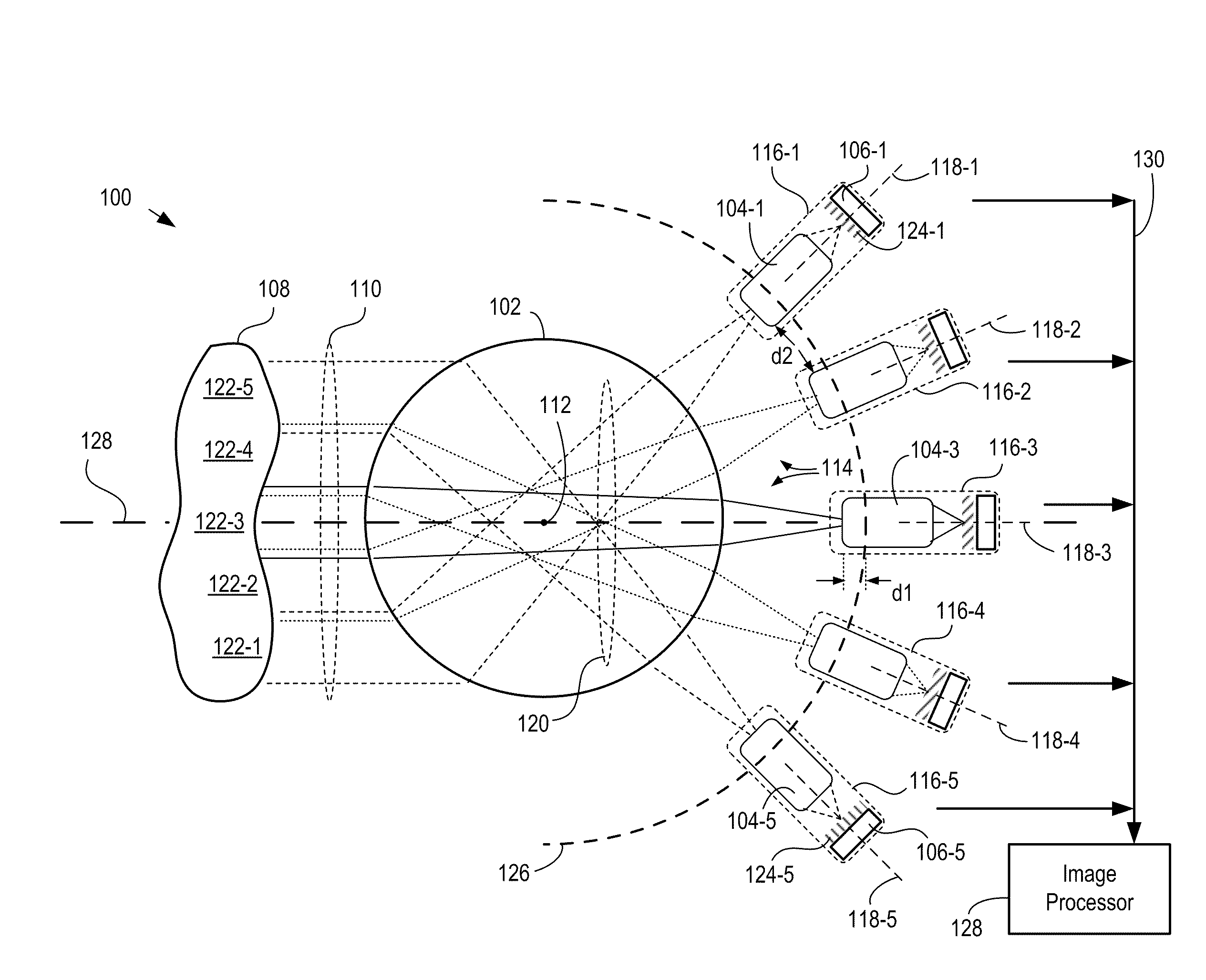
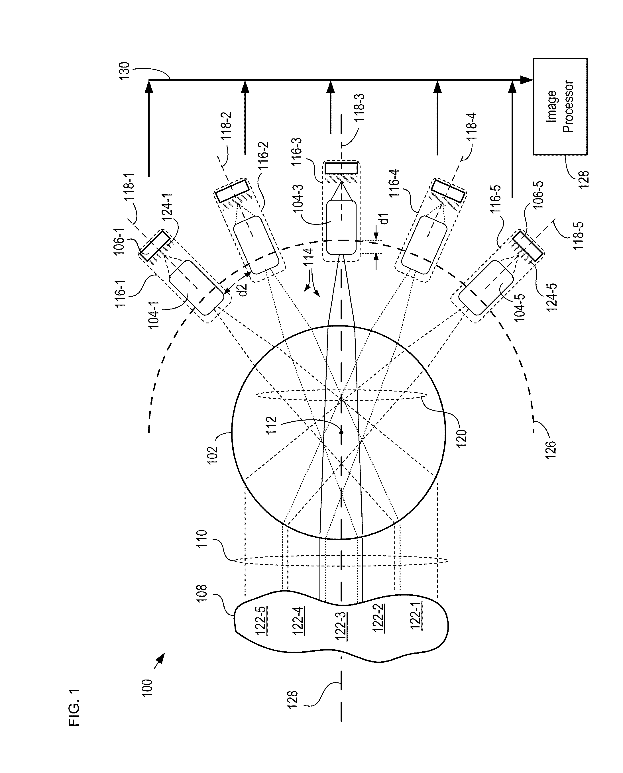
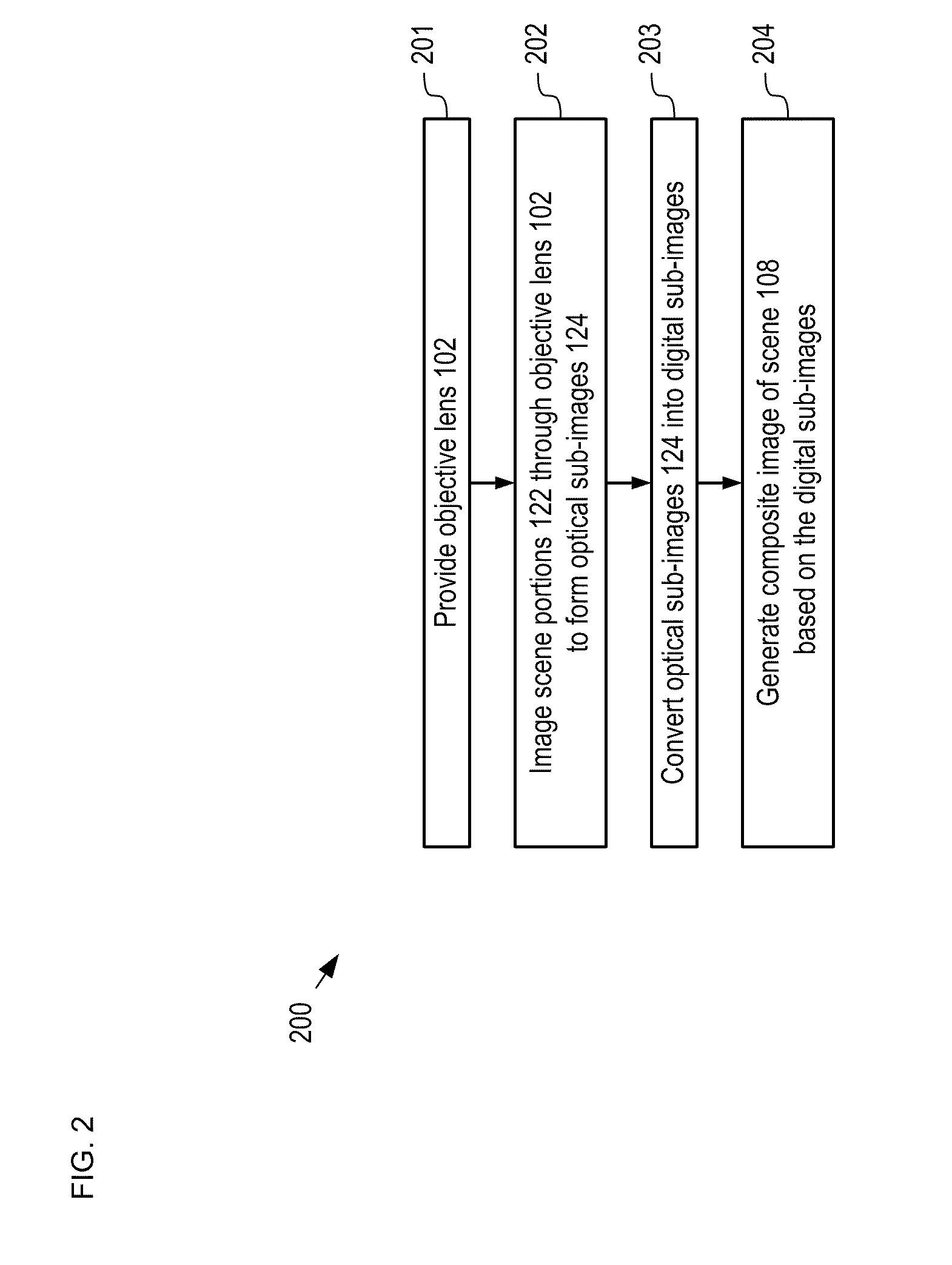
[0040]As disclosed in the parent case, a multi-scale optical system comprises a single objective lens and an array of small secondary lenses. The objective lens and the secondary lenses collectively image a scene onto a plurality of sensor arrays, such as photodetector arrays, as a plurality of optical sub-images. Each secondary lens has a...


PUM


Abstract

A monocentric lens-based multi-scale imaging system is disclosed. Embodiments of the present invention comprise a monocentric lens as an objective lens that collects light from a scene. Monocentric lenses in accordance with the present invention include a spherical central lens element and a plurality of lens shell sections that collectively reduce at least one of spherical and chromatic aberration from the magnitude introduced by the spherical lens element itself. A plurality of secondary lenses image the scene through the objective lens and further reduce the magnitude of aberrations introduced by the objective lens. A plurality of sensor arrays converts optical sub-images of the scene into a plurality of digital images, which can then be used to form a composite image of the scene.

Description

CROSS REFERENCE TO RELATED APPLICATIONS[0001]This case is a continuation-in-part of co-pending U.S. patent application Ser. No. 12 / 651,894 (Attorney Docket: 524-005US) filed 4 Jan. 2010, which is incorporated herein by reference in its entirety.[0002]This application also claims the benefit of U.S. Provisional Patent Application Ser. No. 61 / 328,213, filed Apr. 27, 2010, entitled “Monocentric Lenses for Multi-scale Optical Systems and Methods of Use,” (Attorney Docket: DU3409PROV), which is incorporated herein by reference in its entirety.FIELD OF THE INVENTION[0003]The present invention relates to optics in general, and, more particularly, to imaging systems.BACKGROUND OF THE INVENTION[0004]A digital camera system is normally based on a lens system comprising a number of optical elements that image a scene onto an array of optoelectronic detector elements. As digital camera systems have evolved, these optical elements and detector arrays have been becoming progressively smaller. Unf...

Claims


Application Information

Patent Timeline
IPC IPC(8): H04N5/225
CPCG02B13/06G02B27/0025H04N5/2254H04N5/37213G02B13/006H04N5/247H04N5/2624H04N23/55H04N23/45H04N23/90H04N25/713G02B3/00G02B13/0095G02B2003/0093G06T5/50G06T2207/10016H04N5/265
Inventor MARKS, DANIELBRADY, DAVID JONES
Owner DUKE UNIV
Why Eureka
Try Eureka