High-strength rectangular wire veneer tie and anchoring systems utilizing the same

a technology of rectangular wire veneer and high-strength rectangular wire, which is applied in the direction of building components, building types, constructions, etc., can solve the problems of failure of anchoring systems, failure of above anchoring systems, etc., and achieves the effect of improving the volumetric occupancy of the bed joint, reducing the risk of failure, and simplifying seismic and non-seismic high-strength installations

Active Publication Date: 2014-09-16
HOHMANN & BARNARD INC
View PDF197 Cites 29 Cited by
  • Summary
  • Abstract
  • Description
  • Claims
  • Application Information

AI Technical Summary

Benefits of technology

[0046]It is another object of the present invention to provide labor-saving devices to simplify seismic and nonseismic high-strength installations of brick and stone veneer and the securement thereof to an inner wythe.
[0047]It is yet another object of the present invention to provide a veneer tie that increases volumetric occupancy in the bed joint.
[0048]It is a further object of the presen...

Problems solved by technology

Prior tests have shown that failure of anchoring systems frequently occur at the juncture between the pintle of the veneer tie and the receptor portion of the wall anchor.
On the other hand, contractors find that heavy wire anchors, with diameters approaching the mortar lay...

Method used


Image

  • High-strength rectangular wire veneer tie and anchoring systems utilizing the same
  • High-strength rectangular wire veneer tie and anchoring systems utilizing the same
  • High-strength rectangular wire veneer tie and anchoring systems utilizing the same

Examples


first embodiment

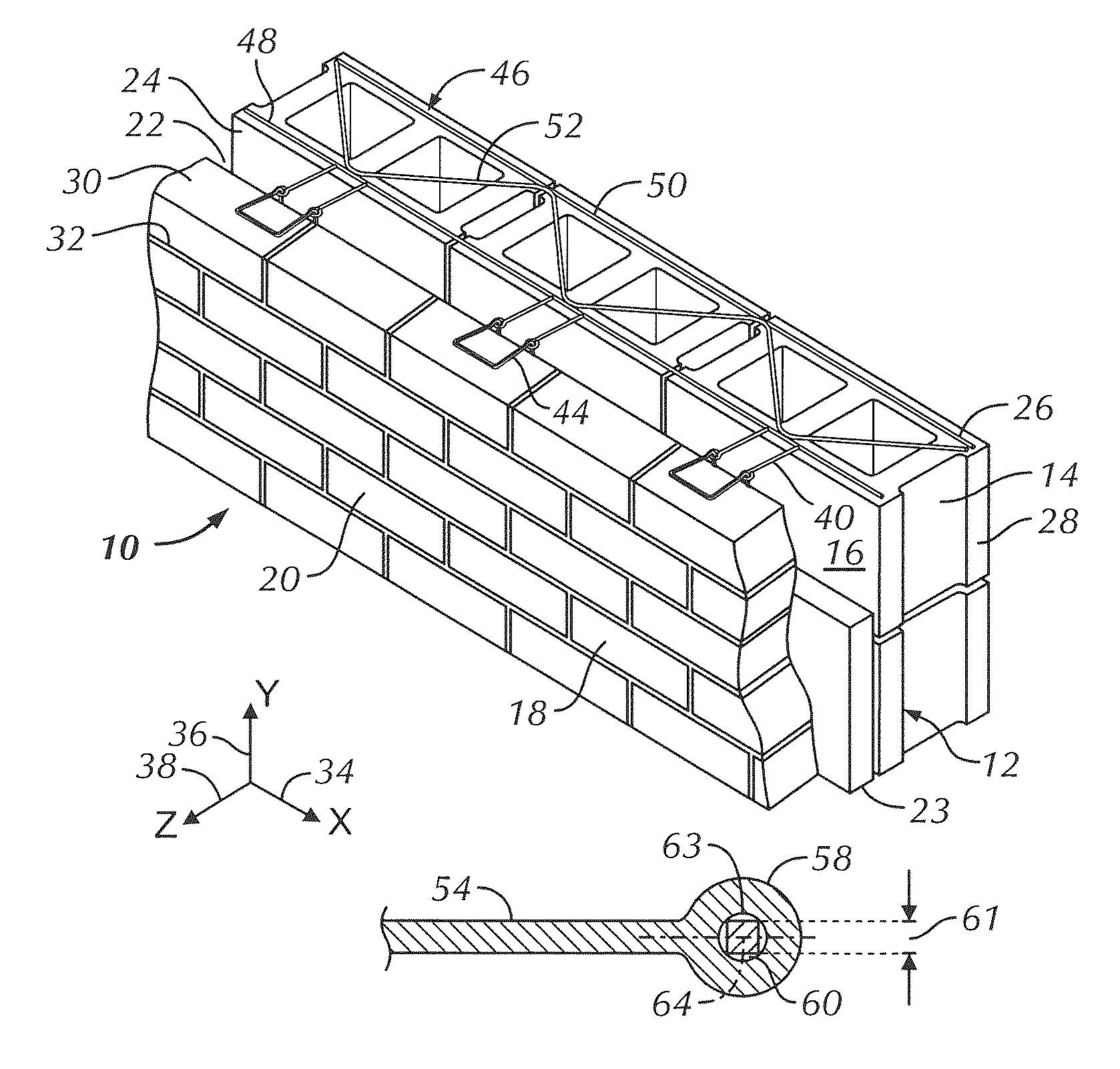
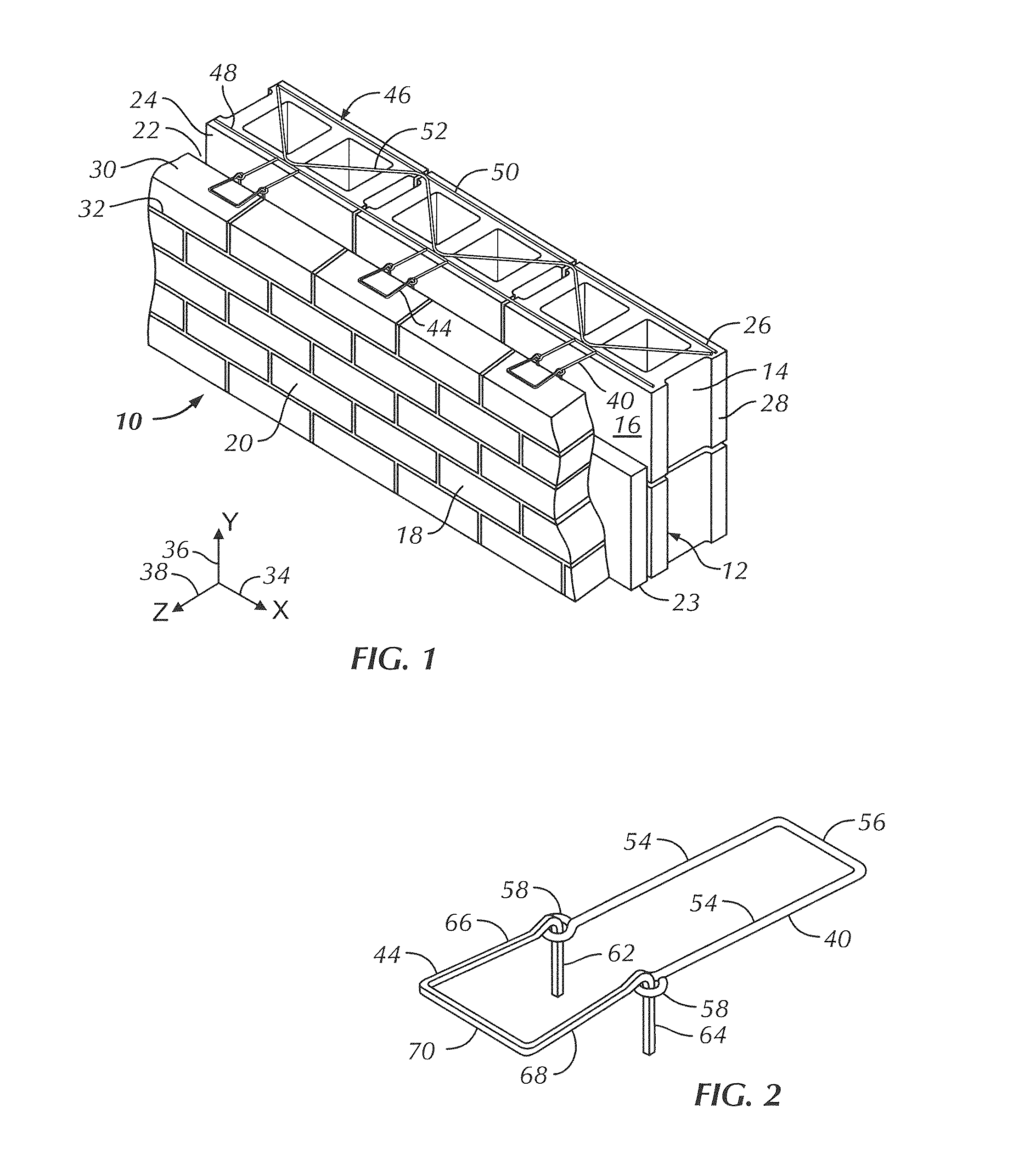
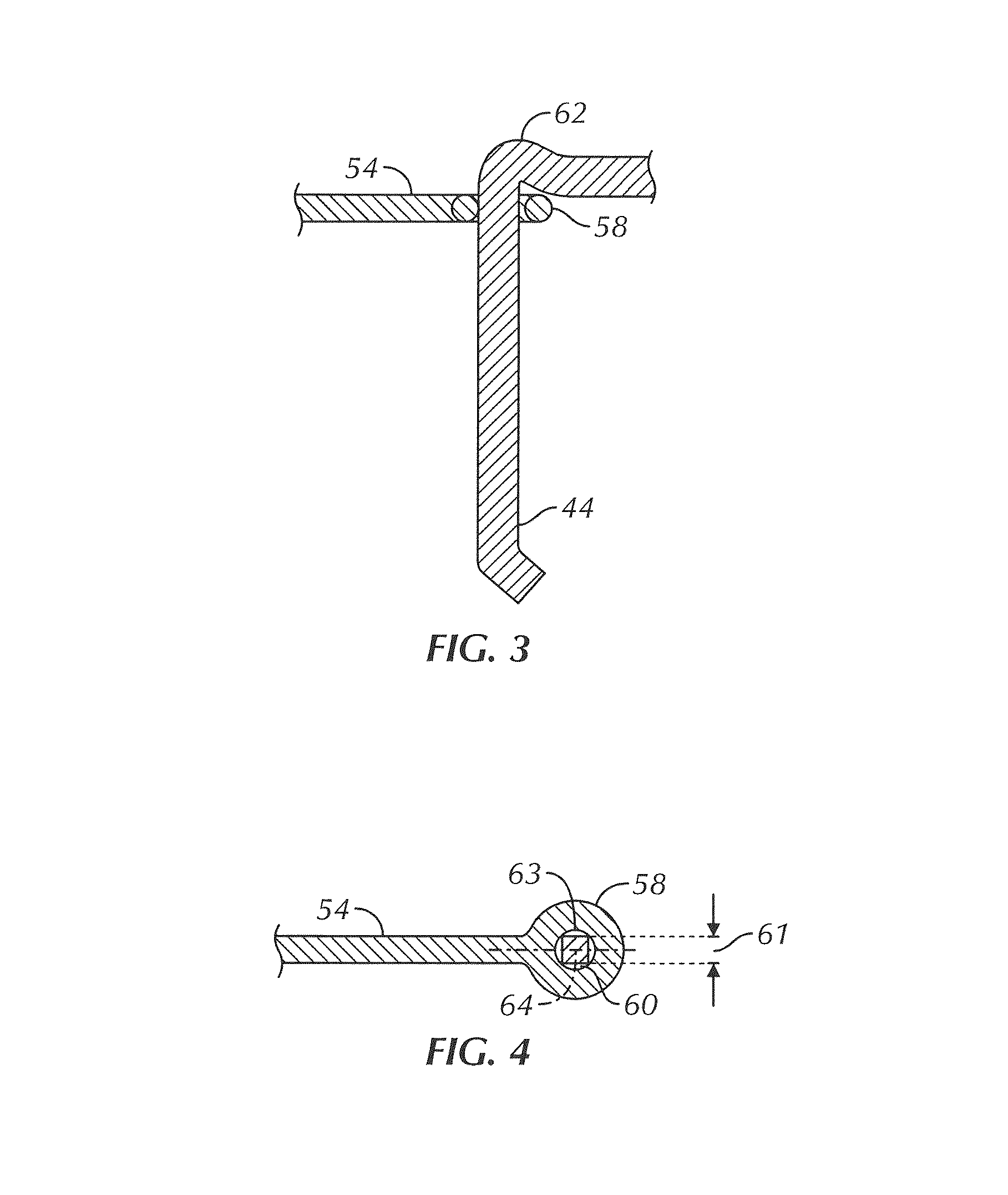
[0067]The description which follows is of three embodiments of anchoring systems utilizing the pintle veneer tie devices of this invention, which devices are suitable for nonseismic and seismic cavity wall applications. Two of the embodiments apply to cavity walls with masonry block inner wythes, and the remaining embodiment to a cavity wall with a dry wall (sheetrock) inner wythe. The wall anchor of the first embodiment is adapted from that shown in U.S. Pat. No. 6,789,365 of the inventors hereof

[0068]Referring now to FIGS. 1 through 4 and 9 the first embodiment of the anchoring system hereof including a high-strength veneer tie of this invention is shown and is referred to generally by the number 10. In this embodiment, a wall structure 12 is shown having a backup wall or inner wythe 14 of masonry blocks 16 and a veneer facing or outer wythe 18 of facing brick or stone 20. Between the backup wall 14 and the facing wall 18, a cavity 22 is formed, which cavity 22 extends outwardly f...

second embodiment

[0080]Referring now to FIGS. 3 through 7 and 9, the high-strength anchoring system is shown and is referred to generally by the numeral 110. The system 110 employs a sheetmetal wall anchor 140. The dry wall structure 112 is shown having an interior wythe 114 with wallboard 116 as the interior and exterior facings thereof. An exterior or outer wythe 118 of facing brick 120 is attached to dry wall structure 112 and a cavity 122 is formed therebetween. The dry wall structure 112 is constructed to include, besides the wallboard facings 116, vertical channels 124 with insulation layers 126 disposed between adjacent channel members 124. Selected bed joints 128 and 130 are constructed to be in cooperative functional relationship with the veneer tie described in more detail below.

[0081]For purposes of discussion, the exterior surface 125 of the interior wythe 114 contains a horizontal line or x-axis 134 and an intersecting vertical line or y-axis 136. A horizontal line or z-axis 138 also pa...


PUM


Abstract

A high-strength rectangular pintle veneer tie and cavity wall anchoring system employing the same is disclosed. The rectangular wire formative construct optionally includes a square cross-section that provides greater volumetric occupancy than that of a similar diameter circular wire formative. The interengaging portions and insertion portion are optionally compressed for greater strength and the rectangular shaped interengaging portion provides a locking interconnection within the anchor precluding significant movement lateral with or normal to the inner wythe.

Description

BACKGROUND OF THE INVENTION[0001]1. Field of the Invention[0002]This invention relates to an improved anchoring arrangement for use in conjunction with cavity walls having an inner wythe and an outer wythe. More particularly, the invention relates to construction accessory devices, namely, veneer ties with high-strength rectangular wire veneer ties. The veneer ties are for emplacement in the outer wythe and are further accommodated by receptors in the cavity, which receptors extend from the inner wythe to capture the specially configured pintles hereof. The invention is applicable to structures having an outer wythe of brick or stone facing in combination with an inner wythe of either masonry block or dry wall construction.[0003]2. Description of the Prior Art[0004]In the past, investigations relating to the effects of various forces, particularly lateral forces, upon brick veneer masonry construction demonstrated the advantages of having high-strength wire anchoring components embe...

Claims


Application Information

Patent Timeline
IPC IPC(8): E04B1/98E04H9/02E04B1/41
CPCE04B1/4178E04B1/98
Inventor HOHMANN, JR., RONALD, P.
Owner HOHMANN & BARNARD INC
Why Eureka
Try Eureka