Floor covering with interlocking design

a technology of interlocking design and floor covering, which is applied in the field of surface coverings, can solve the problems of high adhesive cost, high installation cost, and high installation cost of full-spread adhesive, and achieve the effects of high adhesive cost, high adhesive cost, and high installation cos

Active Publication Date: 2014-09-16
VÄLINGE INNOVATION AB
View PDF136 Cites 117 Cited by
  • Summary
  • Abstract
  • Description
  • Claims
  • Application Information

AI Technical Summary

Benefits of technology

[0208]The present invention further relates to a floor formed by connecting two or more floor planks together using the mechanical lock system of the present invention. The present invention further relates to a method of connecting various pieces of floor plank together to form a surface covering. An advantage of the present invention is that one does not need to lift previously connected pieces in order to install a new piece which can be very typical with many laminate flooring profiles. With the present invention, the long edge (or side) or the short edge (or side) can be installed first without any problem or need to lift or move a previously-installed flooring plank. Furthermore, with the present invention, if a plank is mis-installed for any reason or if the floor needs to be lifted, the planks can be separated from each other using some pull force, but the floors can be reconnected and essentially maintain the same connecting strength that previously existed.
[0209]The present invention includes the following aspects / embodiments / features in any order and / or in any combination:
[0210]1. The present invention relates to a floor plank comprising:
[0211]a resilient composite sheet having four sides, an upper surface, a lower surface, and an overall thickness, and said composite sheet comprising at least one base layer, wherein said at least one base layer comprising at least one polymeric material and at least one filler,
[0212]wherein opposite sides of the composite sheet comprise a first tongue on a first side and a first groove on the opposite second side, wherein the first tongue and first groove have complementary shape to each other to be interlockingly engageable with a corresponding groove or tongue on an adjacent floor plank, and
[0214](a) wherein said first tongue having a first tongue length (TL) measured between the first side of the composite sheet and a distal end of the first tongue, wherein the ratio of the first tongue length (TL) to the composite sheet overall thickness (CSt) is at least about 1.5,

Problems solved by technology

The installation process of using full-spread adhesive is very time consuming, costly, messy as well as cumbersome.
Furthermore, the adhesive cost can be quite expensive.
While this mechanical laminate flooring system has gained great popularity in the United States, there are several problems with this type of flooring.
First, the flooring can be extremely heavy since the core of the floor plank is typically made out of a wood-based material, such as a lignocellulosic-resin composite material, such as high density fiber board or particle board.
Further, this fiber or particle board is typically not water resistant and also can be insufficiently resistant to even humidity changes.
Thus, the laminate flooring can be limited where it is used since if the wood-based core became moist and swelled, this would damage the flooring and the laminate joined floor planks would actually separate.
While some attempts have been made to provide flooring surfaces made out of vinyl that simulate floor planks, these designs have not addressed all of the problems associated with previous flooring products, such as the location of adhesives, failure to use mechanical locking systems, design features that permit easy joining of flooring planks together, and the like.
The designs of the indicated publication are believed to have disadvantages in installation or joint strength.
This process may require using a tapping block or other devices with a hammer, which adds complexity for the installer and also increases the risk of damaging the product.
On the contrary, if the tongue is thin to permit flexing for ease of connection, this can result in weak joint strength.
In the indicated publication, FIGS. 2b, 2c and 2d show no sloped, inclined land in the groove to restrict the tongue from sliding apart from the groove after engagement which can result in a very weak joint strength.
The typical joint strength of this type of design is less than 5 pounds of force per linear inch (pli). FIG. 2e of the indicated publication is expected to have even more problems for similar reasons.
The plastic flooring of the '820 patent is made from hard plastic and is not flexible.
In the designs of the '820 patent, many sharp edges in the tongue and groove profiles are used, and this can generate problems with fit during installation.
In addition, the groove lip top surface plan of the designs in the '820 patent are horizontal, which can make insertion of the tongue into the groove difficult, which can be an especially important problem when inserting short ends of a panel in the short ends of an already engaged adjoining panel.
A disproportionate groove deck area at the tongue tip area will not permit overloading of the void.

Method used


Image

  • Floor covering with interlocking design
  • Floor covering with interlocking design
  • Floor covering with interlocking design

Examples


example 1

[0296]Various floor planks of the present invention were made having a square edge design such as illustrated in FIG. 16.

[0297]The formulations are set forth in Tables 1 and 2 below. An LVT design is illustrated in this example. The plank is formed as two sheets with two base layers provided in a first sheet and a third base layer used as a second sheet that is consolidated with the first sheet in forming the plank. Rectangular shaped pieces with flat edges on all four sides having the dimensions, or slightly larger dimensions, as indicated for planks 1 and 2 in Table 1 are punched out from the consolidated sheet.

[0298]Planks formed with these formulations and constructions are milled to have edge profiles on the width and longitudinal sides have tongue and groove profiles such as shown in FIG. 16 herein, wherein Tg=0.061 inch, H=0.037 inch, Tt=0.054 inch, Tt′=0.089 inch, H′=0.037 inch, Tg / Tt′=0.685, CSt=0.158 inch (4.0 mm), TL=0.270 inch, and TL / CSt=1.71. Equipment for imparting th...

example 2

[0305]A floor plank of the present invention was made having the square edge design such as illustrated in FIG. 37.

[0306]The formulation is set forth in Tables 3 and 4 below. A VCT design is illustrated in this example. The plank is formed as a single sheet. Rectangular shaped pieces with flat edges on all four sides having the dimensions, or slightly larger dimensions, as indicated for planks 3 and 4 in Table 3 are punched out from the consolidated sheet.

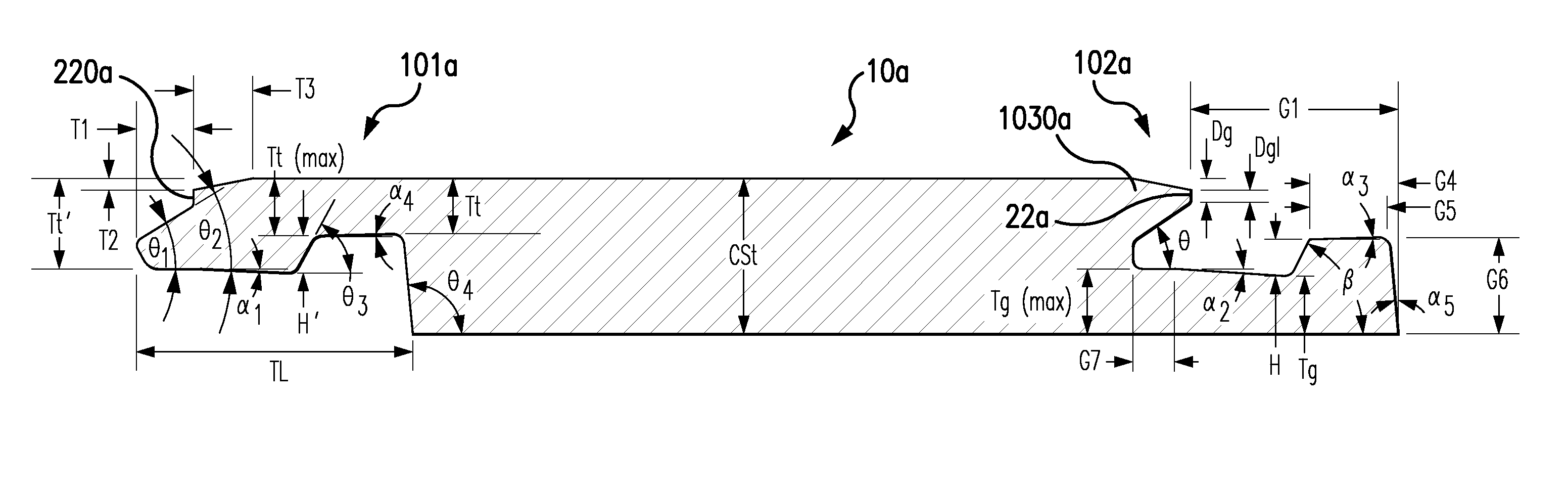
[0307]Planks formed with these formulations and constructions are milled to have edge profiles on the width and longitudinal sides have tongue and groove profiles such as shown in FIG. 37 herein, wherein CSt=0.122 inch (3.1 mm), Tg=0.041 in., Tg(maximum)=0.048 in., H=0.037 in., Dg=0.015 in., angle θ=28°, θ5=30.29°, angle α2=2.29°, angle α3=2.00°, angle α5=5.00°, angle β=63.10°, G1=0.274 in., G4=0.085 in., G6=0.080 in., G7=0.052 in., H=0.037 in., Tt=0.040 in., Tt′=0.073 in., Tg / Tt′=0.56, H′=0.037 in., TL=0.337 in., TL / CSt=2.76, T1=0...

example 3

[0313]Non-grouted VCT floor tiles were made as 3 mm (CSt) tiles, which had the profiled edge design and dimensions shown in FIG. 12 and described herein. For these tiles, the VCT material was modified to include a higher level of vinyl material in the composition than the formulation shown in Example 2, and were punched into 16 inch×16 inch square-shaped tiles in one production run, and 12 inch×12 inch square-shaped tiles in another production run, but otherwise the manufacture of the tiles was substantially similar to that described for the VCT material of Example 2.

[0314]The formulation of the VCT material used for this example is shown in Table 5. All component amounts indicated in Table 5 are weight percentages.

[0315]

TABLE 5FormulationSingle BaseLayer, amt.Ingredientsin wt %.PVC25%-28%Plasticizer10%-23%Filler55%-80%Stabilizer1%-3%Pigments0.1%-2% 

[0316]The tile products were easily installable and formed strong joints. The floor tiles had the properties previously described.


PUM

PropertyMeasurementUnit
lengthaaaaaaaaaa
lengthaaaaaaaaaa
widthaaaaaaaaaa

Abstract

Surface coverings, such as floor coverings, with an interlocking design are described. Methods of making the surface coverings are further described.

Description

[0001]This patent application claims the benefit of U.S. Provisional Patent Application No. 61 / 293,831 filed Jan. 11, 2010, and is incorporated in its entirety by reference herein.BACKGROUND OF THE INVENTION[0002]The present invention relates to surface coverings including floor coverings. The present invention more particularly relates to surface coverings, such as floor coverings having an interlocking design to connect individual pieces of floor plank or tile together. The present invention further relates to methods of making the surface covering.[0003]Some of the current surface coverings, such as vinyl floor coverings, are typically laid down by placing an adhesive underneath the floor covering or on the sub-floor or on the underlayment in order to secure the floor covering. In resilient floor coverings, a large piece of resilient floor covering is typically cut in order to fit the dimensions of the room. The resilient floor coverings can often be 12-foot wide and can be any l...

Claims


Application Information

Patent Timeline
Patent Type & Authority Patents(United States)
IPC IPC(8): E04B2/00E04B2/32E04F15/02
CPCE04F15/02005E04F15/02033E04F15/02E04F2201/0153E04F15/02038E04F15/105E04F2201/0161E04F15/02016E04F15/107B32B3/06B32B5/024B32B5/18B32B5/245B32B7/12B32B2255/02B32B2266/0235B32B2419/04E04F15/0215E04F15/102
Inventor WHISPELL, JOHN M.CHEN, HAO A.
Owner VÄLINGE INNOVATION AB
Why Eureka
Try Eureka