Eureka AIR delivers breakthrough ideas for toughest innovation challenges, trusted by R&D personnel around the world.

Ignition laser

a laser and ignition technology, applied in the field of ignition lasers, can solve problems such as failure of ignition lasers, and achieve the effect of safe and reliable sealing

Inactive Publication Date: 2014-09-16
ROBERT BOSCH GMBH
View PDF18 Cites 6 Cited by
  • Summary
  • Abstract
  • Description
  • Claims
  • Application Information

AI Technical Summary

Benefits of technology

The invention provides an ignition laser that has a sealed combustion chamber window, which ensures a longer lifespan and safety.

Problems solved by technology

In other words, if exhaust gases went from the combustion chamber into the interior of the ignition laser, this would lead to failure of the ignition laser.

Method used


Image

  • Ignition laser
  • Ignition laser
  • Ignition laser

Examples


Embodiment Construction

[0035]On the basis of the figures, the ignition device according to an example embodiment of the present invention is explained in an internal combustion engine as an example. However, the ignition laser may also be implemented in a gas turbine.

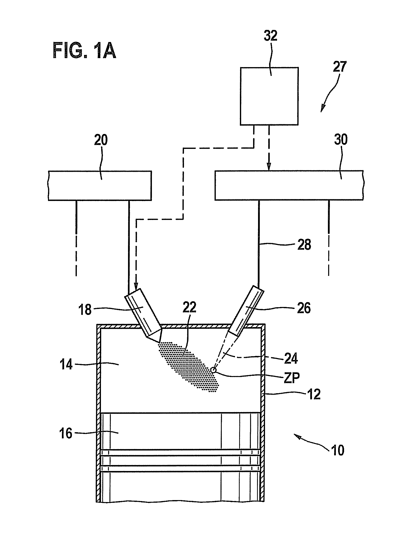
[0036]An internal combustion engine is labeled on the whole with reference numeral 10 in FIG. 1a. It may be used to drive a motor vehicle (not shown). Internal combustion engine 10 usually includes a plurality of cylinders, only one being labeled with reference numeral 12 in FIG. 1a. A combustion chamber 14 of cylinder 12 is bordered by a piston 16. Fuel enters combustion chamber 14 through an injector 18, which is connected to a pressurized fuel storage 20, known as a rail. Alternatively, the fuel-air mixture may also be formed outside of combustion chamber 14, for example, in the intake manifold.

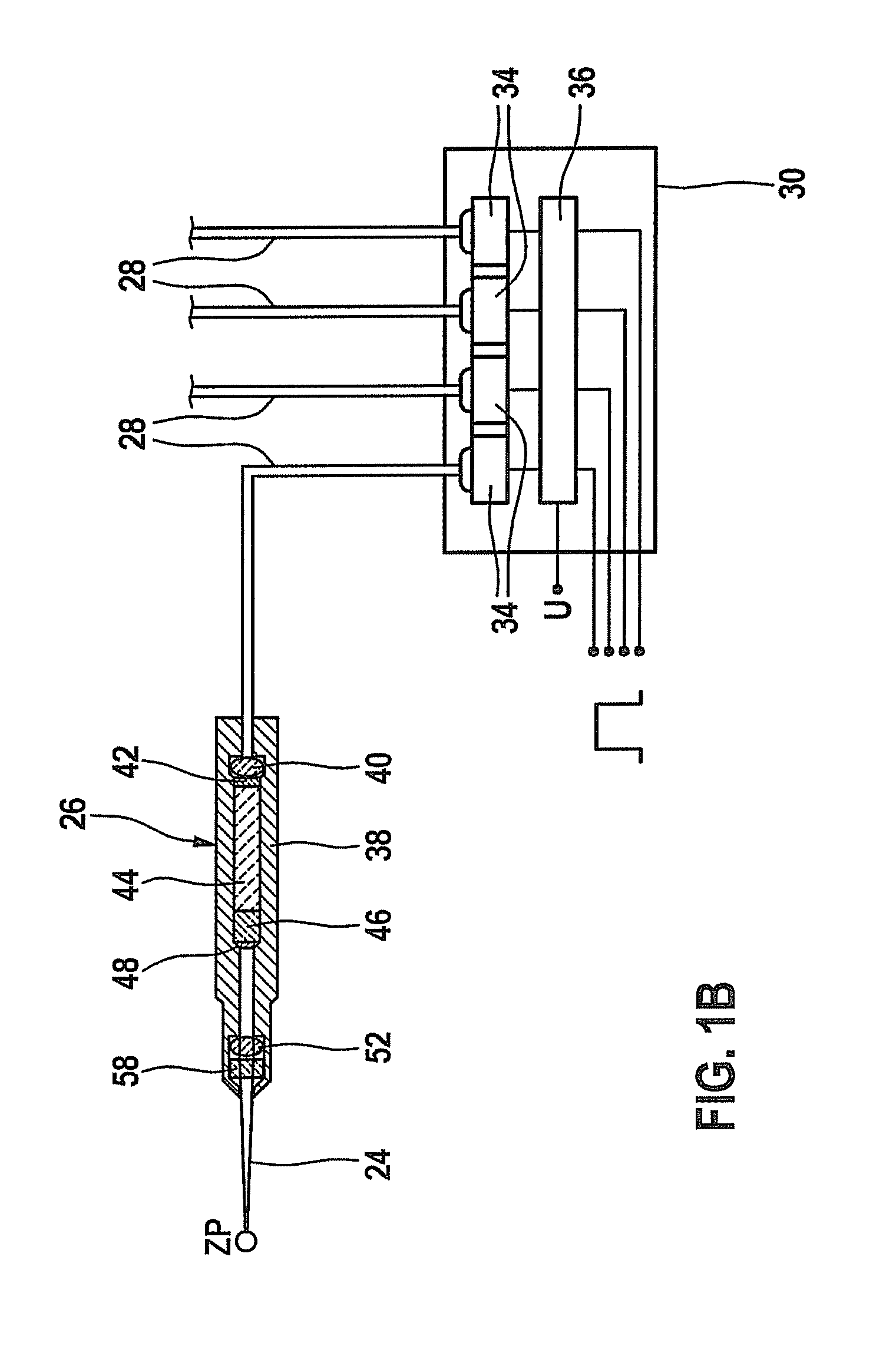
[0037]Fuel-air mixture 22 present in combustion chamber 14 is ignited by a laser pulse 24, which is emitted by an ignition device 27 including an i...


PUM

PropertyMeasurementUnit
wavelengthaaaaaaaaaa

Abstract

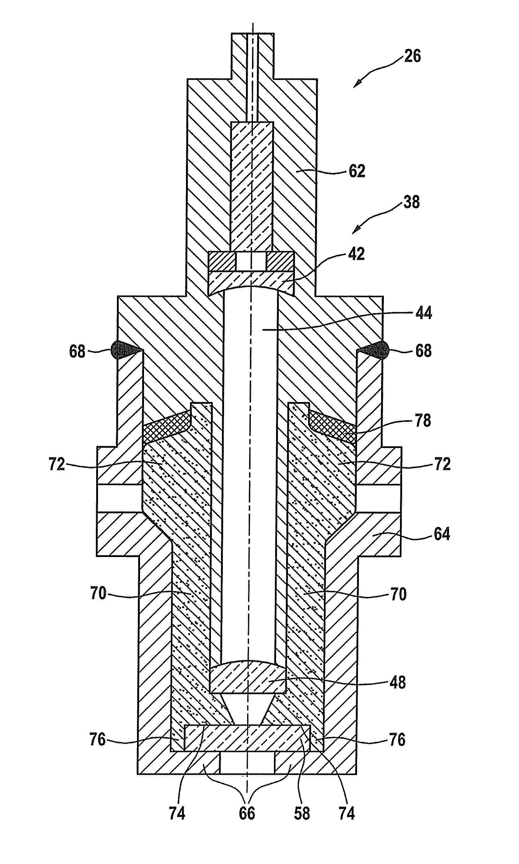
An ignition laser, includes a laser-active solid-state body, a housing and a combustion chamber window, the housing having an inner sleeve and an outer sleeve. An insert is provided between the inner sleeve and the outer sleeve, the insert and the combustion chamber window being joined sealingly and integrally.

Description

FIELD OF THE INVENTION[0001]The present invention relates to an ignition laser.BACKGROUND INFORMATION[0002]WO 2005 / 066488 describes a so-called laser ignition. This laser ignition includes an ignition laser protruding into the combustion chamber of an internal combustion engine. This ignition laser is connected via a light guide device to a pumped light source.[0003]A so-called combustion chamber window, which is transmissive for the laser pulses generated in the ignition laser, is present on one end of the ignition laser facing the combustion chamber. The laser wavelength is between 500 nm and 1500 nm, preferably between 900 nm and 1100 nm. This combustion chamber window must be accommodated in a housing of the ignition laser with a seal. High demands are made of the seal between the combustion chamber window and the housing because surface temperatures of more than 600° C. may occur on the combustion chamber window during operation in an internal combustion engine, for example. In...

Claims


Application Information

Patent Timeline
Patent Type & Authority Patents(United States)
IPC IPC(8): F02P23/04F02C7/264H01S3/00H01S3/02H01S3/113
CPCF02P23/04F02C7/264H01S3/025H01S3/005H01S3/113Y10T29/49002
Inventor WEYL, HELMUTGUETH, MARCOHERDEN, WERNERNUEBEL, KARL-HEINZWETZL, FRANZWEINROTTER, MARTINWOERNER, PASCALHENNECK, STEFANRAIMANN, JUERGENENGELHARDT, JOERG
Owner ROBERT BOSCH GMBH
Why Eureka
Eureka Blog
Learn More