Elastic connection between housing parts of motor-driven power tools

a technology of elastic connection and housing parts, which is applied in the direction of portable power tools, manufacturing tools, drilling machines, etc., can solve the problems of limited strength and the binding of the connecting elemen

Inactive Publication Date: 2014-09-16
ROBERT BOSCH GMBH
View PDF95 Cites 10 Cited by
  • Summary
  • Abstract
  • Description
  • Claims
  • Application Information

AI Technical Summary

Benefits of technology

[0006]It is the object of the invention to embody an elastic connection of the type defined at the outset in such a way that, regardless of its heavy load-bearing capability, it is satisfactory both as a covering element and in damping performance and can be produced economically.
[0009]Advantageously, the connecting element, for instance with a diaphragm-like design, can have high flexibility in its middle portion located between the peripheral portions, or may be designed with a view to strong damping of vibration. This can be attained among other things as well by providing that for the middle portion, a different material from that for the peripheral portions, or a material that is processed differently from that for those portions, is selected.
[0012]Particularly in conjunction with an arrangement of the peripheral region of a particular housing part that is angled or stepped relative to the extension plane, it is possible within the scope of the invention by way of the connecting element also to achieve a connection that is in the same plane as the housing parts but is optionally offset in fluted fashion, without impairing the other functions of the connecting element and / or the strength of the connection between the housing parts.
[0013]In particular, the embodiment of the connection in accordance with the invention is also suitable for being achieved by injection molding, and with the connection of the invention it is possible in particular to attach carrying and / or guiding parts, such as handles or the like, to housing parts, so that given a suitable design of the connecting element, the handle is uncoupled in a vibration-damping way from the housing via the connecting element. Particularly for this last purpose, an annular design of the connecting element, which in the connection between housing parts preferably has a striplike rectilinear course, proves to be practical.

Problems solved by technology

The result for the connecting element is a binding to the respective housing part attached in this way, whose strength is limited in the final analysis only by the strength of the material used for the connecting element and / or the load-bearing capacity of the housing part in the area around the breach.

Method used


Image

  • Elastic connection between housing parts of motor-driven power tools
  • Elastic connection between housing parts of motor-driven power tools
  • Elastic connection between housing parts of motor-driven power tools

Examples


Embodiment Construction

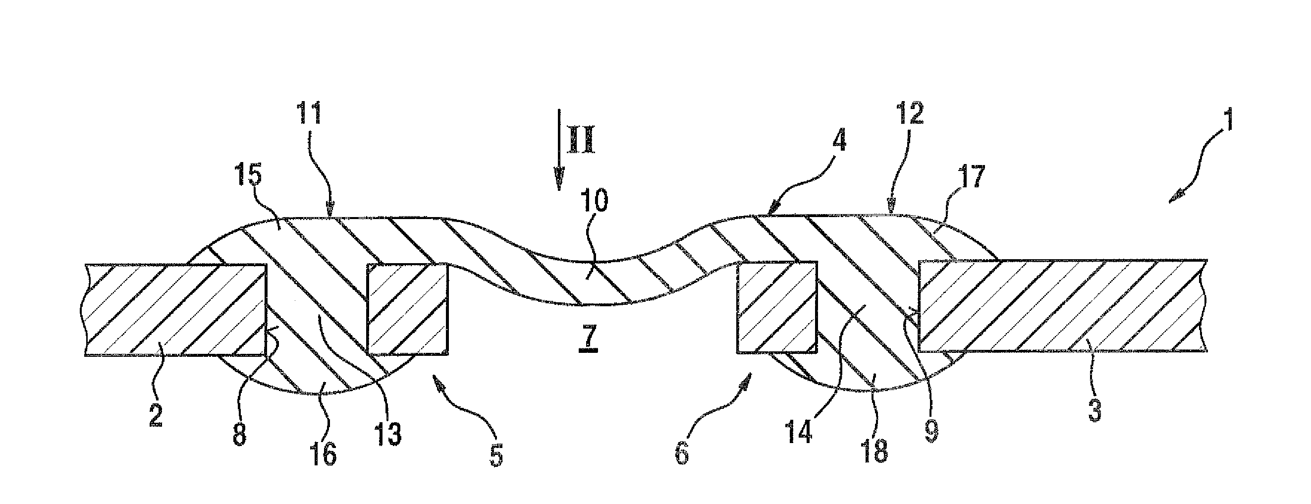
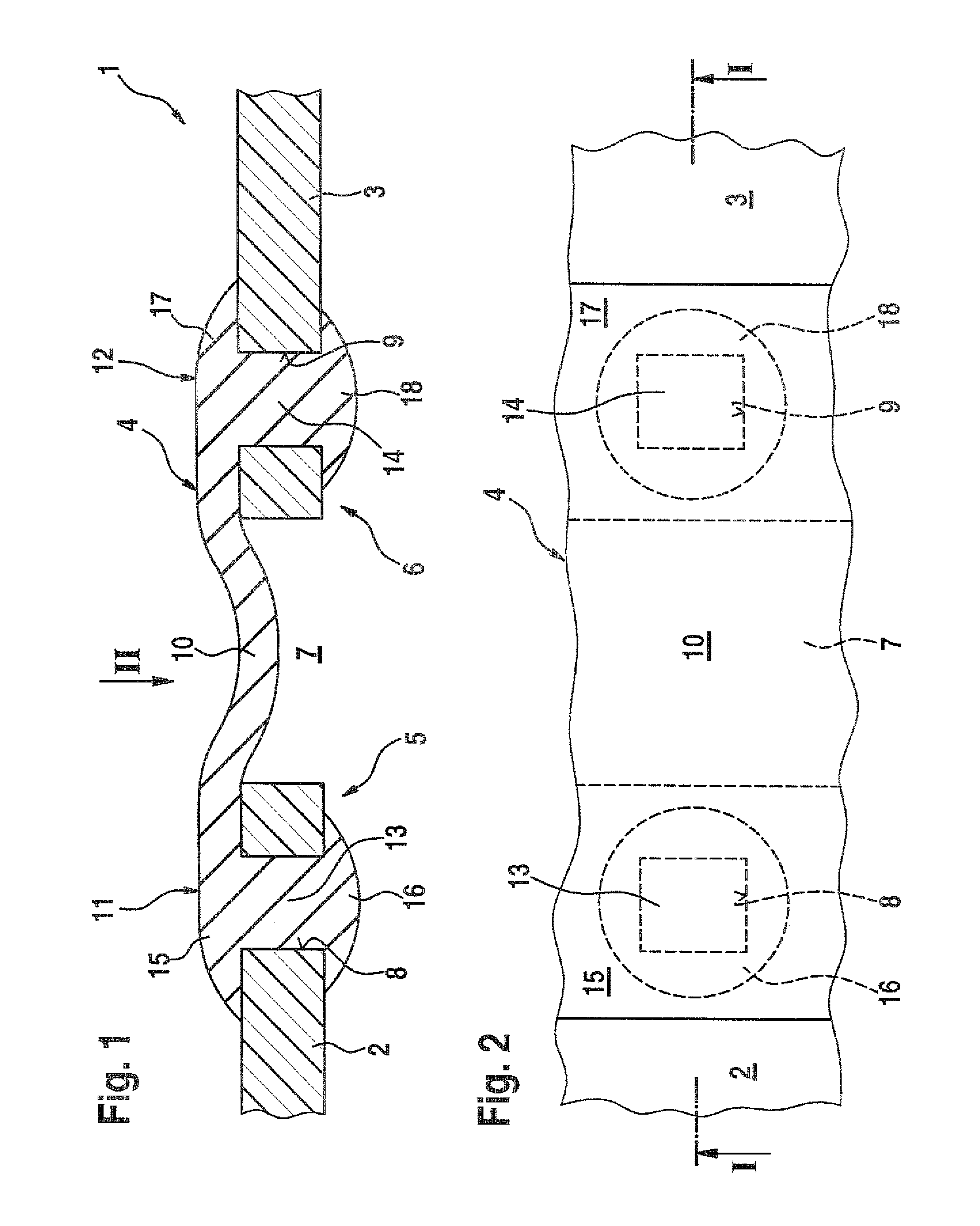
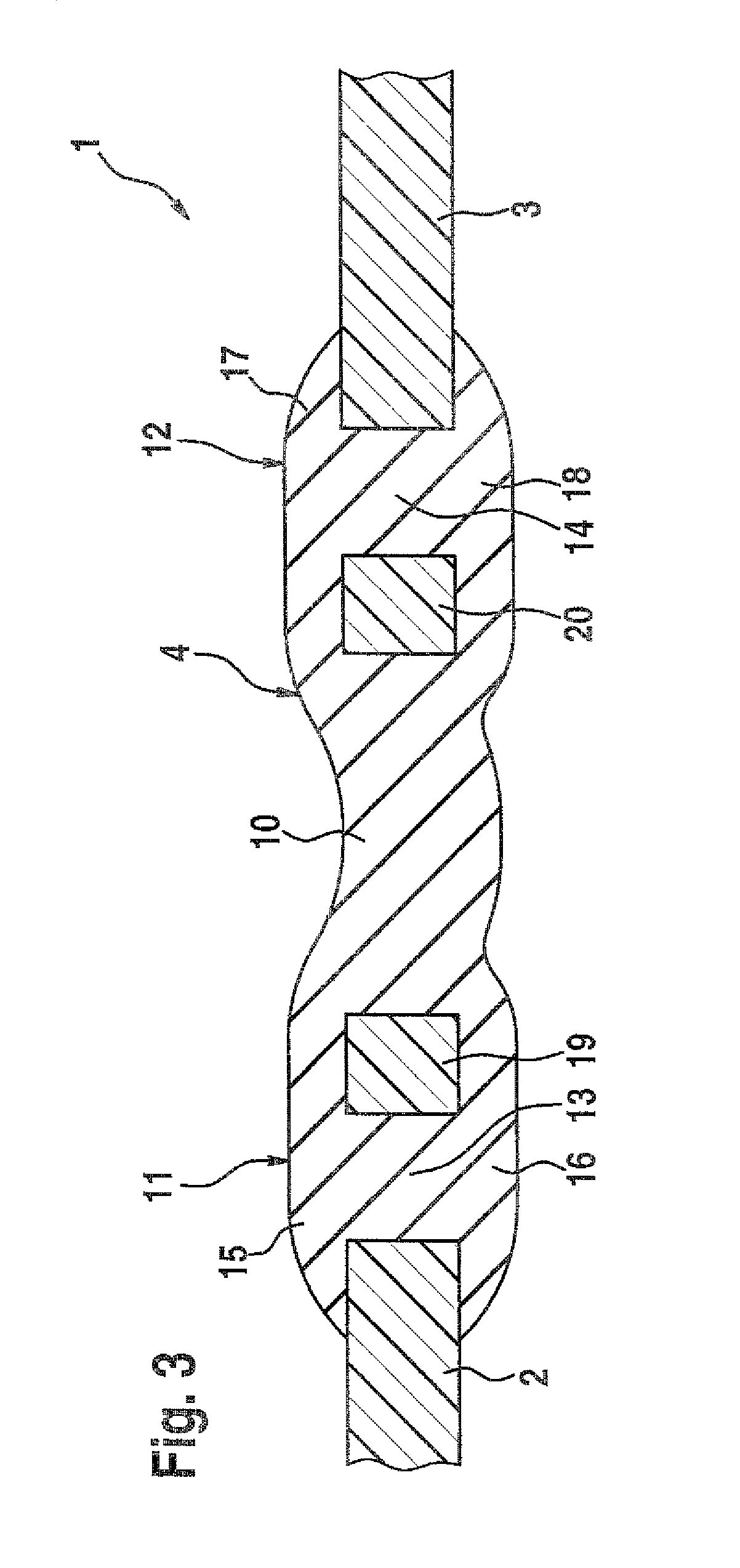
[0022]Of the housing 1 of the power tool, shown here in the form of an electrically powered handheld power tool, FIG. 1 shows a fragment in which two housing parts 2 and 3 are connected to one another via a connecting element 4. The housing parts 2, 3 are shown only with regard to their adjacent peripheral regions 5, 6 extending approximately in the same direction, which are spaced apart from one another via a gap 7 and which near the periphery toward the gap 7 are provided with breaches 8, 9. The breaches 8, 9 are embodied as peripherally closed openings that penetrate the housing parts 2, 3 transversely to their extension plane. The connecting element 4 is connected to these housing parts 2 and 3 in form-locking fashion fitting over the gap 7 and with respect to the exemplary embodiment shown, it is anchored in the same way relative to housing parts 2 and 3.

[0023]The connecting element 4 has a middle portion 10, fitting over the gap 7, which is adjoined by the peripheral portions ...


PUM

PropertyMeasurementUnit
elasticaaaaaaaaaa
damping performanceaaaaaaaaaa
strengthaaaaaaaaaa

Abstract

An elastic connection is established between housing parts of a power-driven machine tool by an elastic connecting element which is attached in form-locking fashion to at least one of the housing parts to be connected, in such a way that the connecting element has a land penetrating a breach of the housing part, and this land connects covering parts of the connecting element that are located in coincidence with the breach.

Description

CROSS-REFERENCE TO RELATED APPLICATION[0001]This application is a 35 USC 371 application of PCT / EP2008 / 055409 filed on May 2, 2008.BACKGROUND OF THE INVENTION[0002]1. Field of the Invention[0003]The invention relates to an elastic connection between housing parts of motor-driven power tools, in particular housing parts of electrically powered handheld power tools.[0004]2. Description of the Prior Art[0005]Elastic connections having an elastic connection element to corresponding peripheral regions of housing parts that is disposed spanning the gap are known in the industry and are used for the most various reasons, such as noise abatement, tolerance compensation, and / or construction simplification; depending on the intended application and on the field of use of the particular power tool, different loads on the elastic connection result, and sometimes, loads that can be mastered only conditionally by conventional structural features have to be mastered as well, requiring that a shift...

Claims


Application Information

Patent Timeline
Patent Type & Authority Patents(United States)
IPC IPC(8): B25D17/11B25D17/24B25F5/00
CPCB25F5/006Y10T403/54
Inventor KRAUTER, JOCHENMAUTE, JOERGWIKER, JUERGEN
Owner ROBERT BOSCH GMBH
Why Eureka
Try Eureka