Mixing syringe

a technology of mixing syringe and syringe, which is applied in the field of medical devices, can solve the problems of inconvenient shaking of the syringe used for injection, unsuitable for mixing pre-mixed solution, and unsuitable for percutaneous procedures, and achieve the effect of eliminating any unused volum

Active Publication Date: 2014-09-16
IKOMED TECH
View PDF197 Cites 8 Cited by
  • Summary
  • Abstract
  • Description
  • Claims
  • Application Information

AI Technical Summary

Benefits of technology

[0008]A movable mixing disc is inserted into a regular syringe. The mixing disc has a small hole covered by a fine screen, allowing only saline solution to get behind disc. When the plunger of the syringe is pressed, the saline solution emerges from the mixing disc hole as a high velocity jet, stirring up the settled particles. As the ejection continues, the mixing disc is pushed forward by the plunger in order to eliminate any unused volume.

Problems solved by technology

Such particles tend to settle very quickly out of the solution as they are heavier than water, causing an uneven concentration of particles during the injection.
It is inconvenient to keep shaking the syringe used for injection, as the whole process is performed in a few seconds and the doctor has to concentrate on injecting the correct amount.
They are not designed to stir up a pre-mixed solution.
Prior art syringes designed to stir-up embolization mixtures, such as disclosed in US2009 / 0247985, are needlessly complex.
Also, many of the prior art mixing syringes are not designed to be filled with the pre-mixed solution just before use.

Method used


Image

  • Mixing syringe
  • Mixing syringe
  • Mixing syringe

Examples


Embodiment Construction

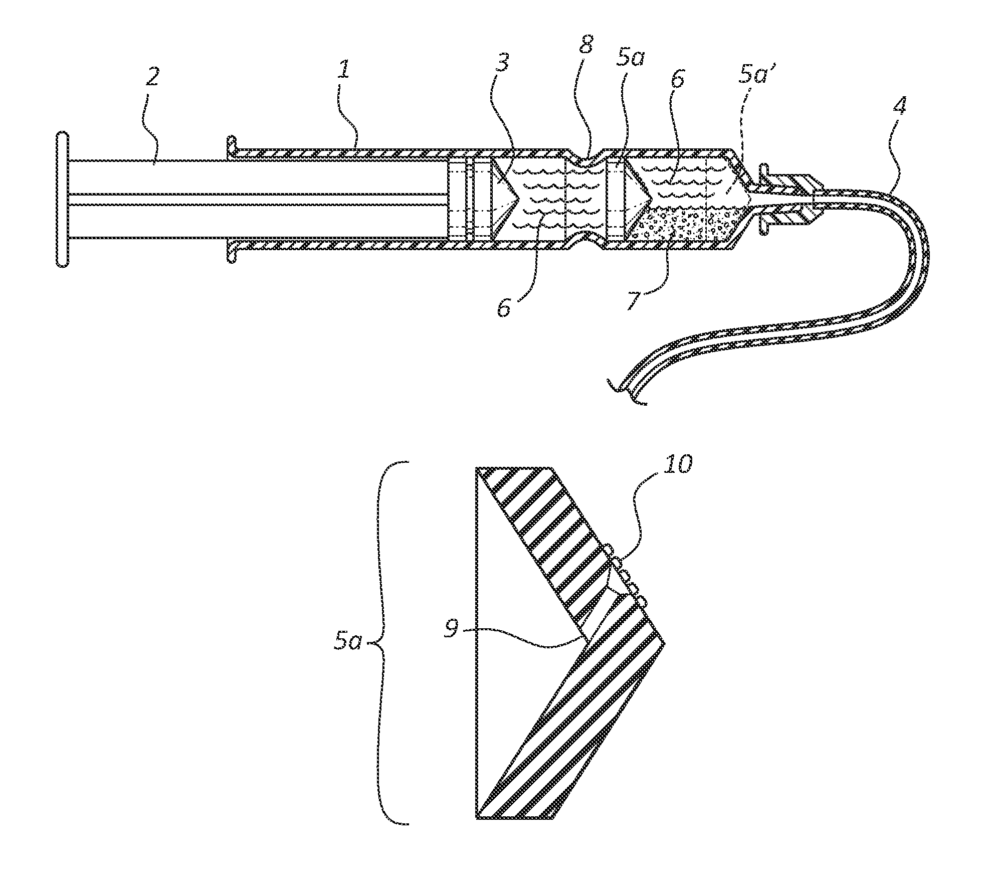
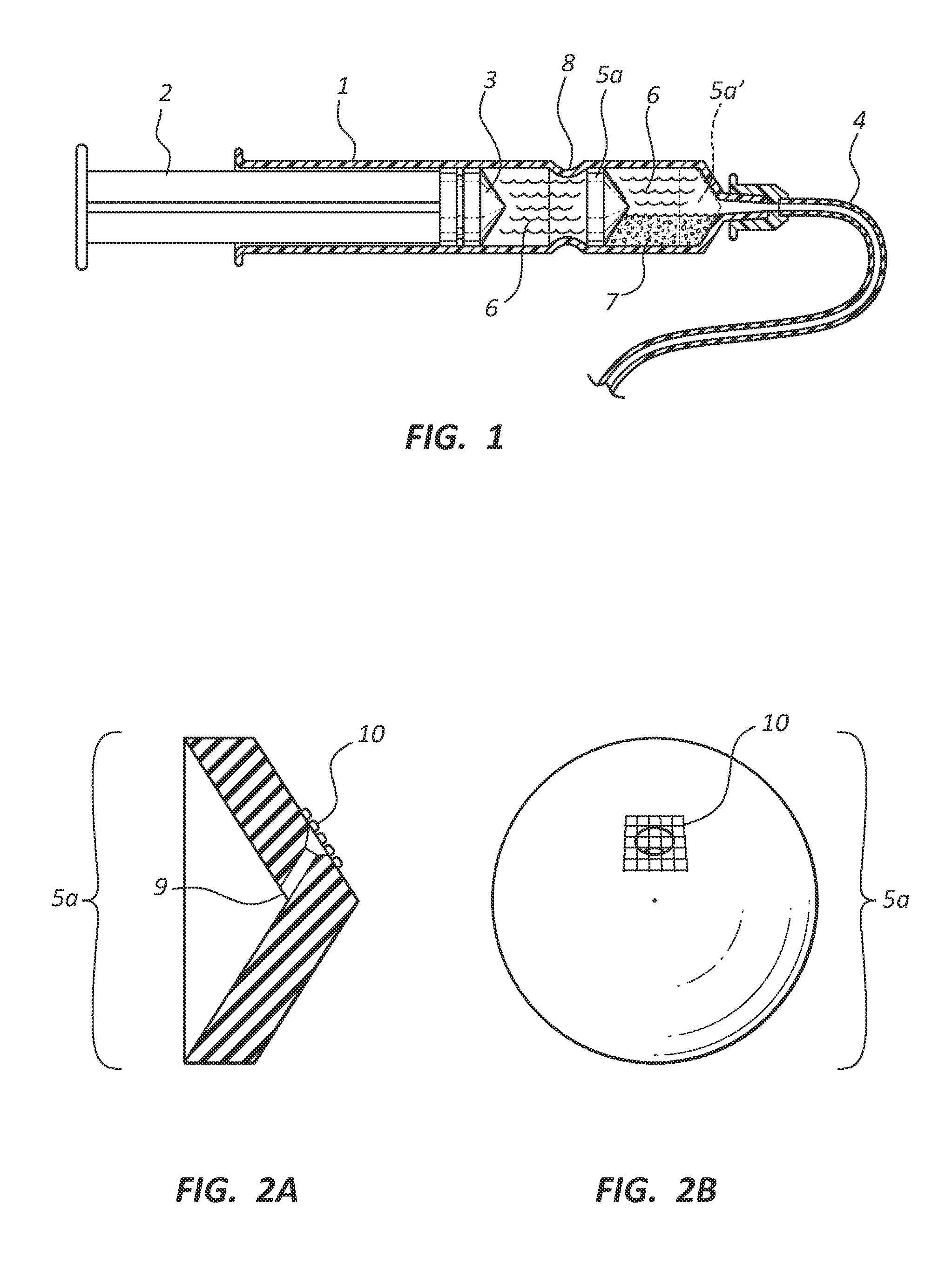
[0016]Referring now to FIG. 1, the mixing syringe is a regular syringe with the addition of a mixing disc. A syringe 1 includes a plunger 2 and a seal 3 in order to eject the liquid 6 via tube 4. A piston-like mixing disc 5a is added into the syringe. The initial position of disc 5a is shown as 5a′, with plunger seal 3 touching disc 5a. As liquid and particles are sucked into syringe 1, seal 3 moves farther from disc 5a to create a vacuum. Disc 5a moves as well, until stopped by slight ridge 8. The size of the ridge is exaggerated in FIG. 1 for clarity. It only needs to reduce the inside diameter by about 0.2-0.3 mm. Flexible seal 3 easily passes over such a ridge. The particles 7 are sucked into the syringe via tube 4 and quickly settle as shown in FIG. 1. The particles do not accumulate in the section between plunger seal 3 and disc 5a as disc 5a includes a filter with pore sizes smaller than the particles. This is shown in FIGS. 2A and 2B. Disc 5a has one or more holes 9 covered ...


PUM


Abstract

A movable mixing disc is inserted into a regular syringe. The mixing disc has a small hole covered by a fine screen, allowing only saline solution to get behind the disc. When the plunger of the syringe is pressed, the saline solution emerges from the mixing disc hole as a high velocity jet, stirring up the settled particles. As the ejection continues, the mixing disc is pushed forward by the plunger in order to eliminate any unused volume.

Description

[0001]The present application claims the benefit under 35 U.S.C. §119(e) of U.S. Provisional Application No. 61 / 632,263 filed on Jan. 23, 2012.FIELD OF THE INVENTION[0002]The invention is in the medical field, and is particularly useful in percutaneous procedures such as embolization.BACKGROUND OF THE INVENTION[0003]In certain medical procedures, such as blood vessel embolization, it is desired to inject particles into the body. The procedure is a minimally invasive alternative to surgery. The purpose of embolization is to prevent blood flow to an area of the body, which effectively can shrink a fibroid, such as a uterine fibroid. It can also shrink a tumour or block an aneurysm. It is typically done by injecting blocking particles into a blood vessel.[0004]The procedure is carried out as an endovascular procedure by a radiologist in an interventional suite. It is common for most patients to have the treatment carried out with little or no sedation, although this depends largely on ...

Claims


Application Information

Patent Timeline
Patent Type & Authority Patents(United States)
IPC IPC(8): A61M5/31
CPCA61M2205/7545A61M5/31A61M2005/31516A61M5/31596A61M5/19A61M2005/31598
Inventor MACHAN, LINDSAY S.GELBART, DANIEL
Owner IKOMED TECH
Why Eureka
Try Eureka