
Magnetic recording medium manufacturing apparatus

a manufacturing apparatus and recording medium technology, applied in the manufacture of record carriers, coatings, special surfaces, etc., can solve the problems of deterioration of the durability of the tribology between the magnetic head and the magnetic recording medium, etc., to prevent the occurrence of linear coating unevenness, reduce the floating height of the magnetic head, and prevent liquid level fluctuation

Active Publication Date: 2014-09-16
RESONAC CORPORATION
View PDF4 Cites 0 Cited by
  • Summary
  • Abstract
  • Description
  • Claims
  • Application Information

AI Technical Summary

Benefits of technology

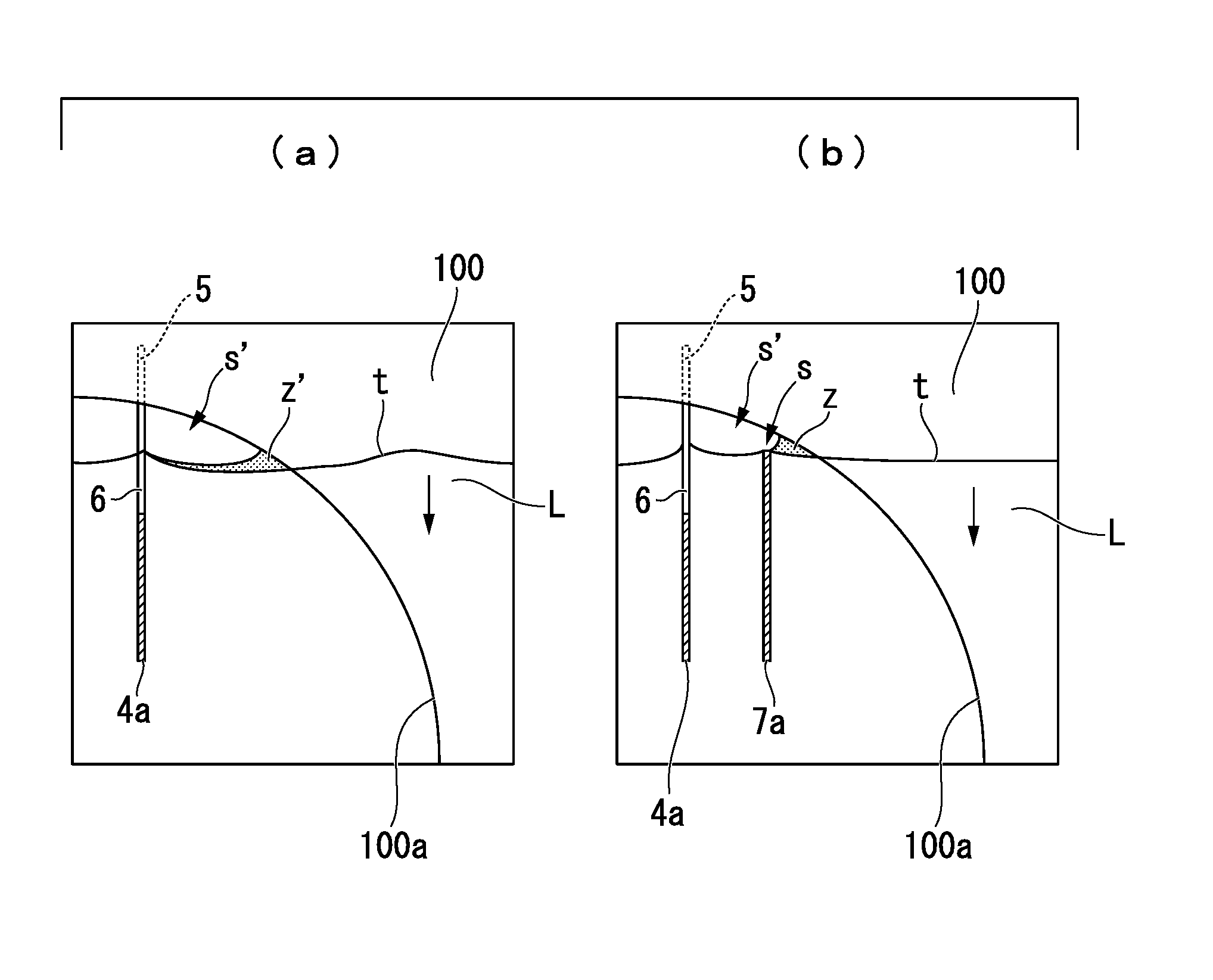
[0021]As described above, in the invention, when the magnetic recording medium is drawn up from the dip tank filled with the liquid lubricant, the baffle plate can prevent fluctuation in the liquid level which occurs when the level of the liquid lubricant is cut by the supporting plate.
[0022]Therefore, according to the invention, it is possible to form a lubricant film with a uniform thickness on the surface of the magnetic recording medium while preventing the occurrence of linear coating unevenness in the thickness distribution of the lubricant film formed on the surface of the magnetic recording medium. As a result, it is possible to provide a magnetic recording medium which is suitable for reducing the floating height of a magnetic head and has high abrasion resistance and high environmental resistance.

Problems solved by technology

Therefore, tribology between the magnetic head and the magnetic recording medium is a critical problem and efforts to improve a protective film formed on a magnetic film of the magnetic recording medium have continued.
However, when only the protective film is provided, the durability of the magnetic recording medium deteriorates.

Method used


Image

  • Magnetic recording medium manufacturing apparatus
  • Magnetic recording medium manufacturing apparatus
  • Magnetic recording medium manufacturing apparatus

Examples


example 1

[0089]In Example 1, a lubricant was applied onto the magnetic recording medium manufactured by the above-mentioned method. Specifically, a coating solution in which a lubricant was dissolved in a solvent was applied by a dip method using a dipping apparatus, thereby forming a lubricant film with a thickness of 1.5 nm on the surface of the protective film of the magnetic recording medium.

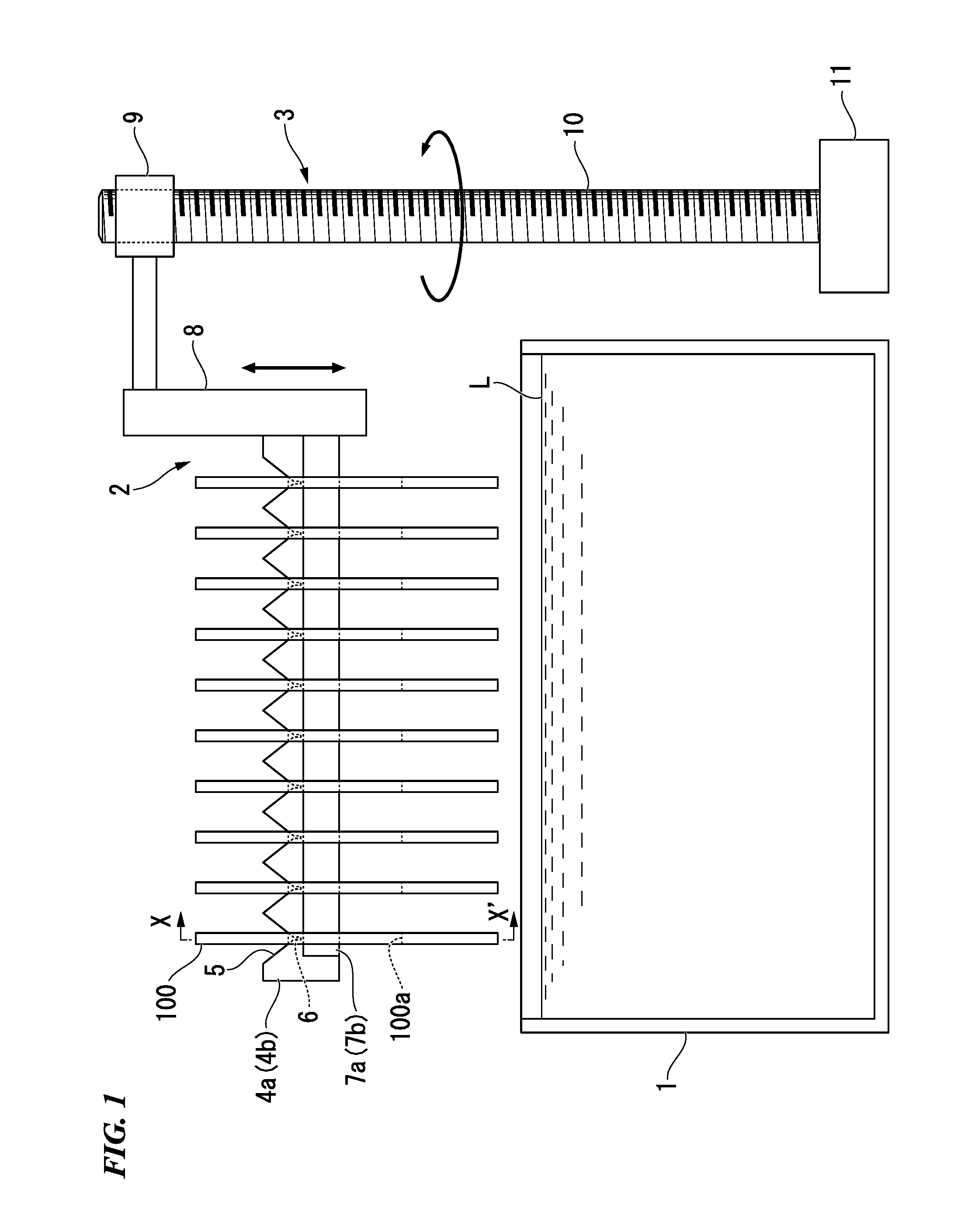
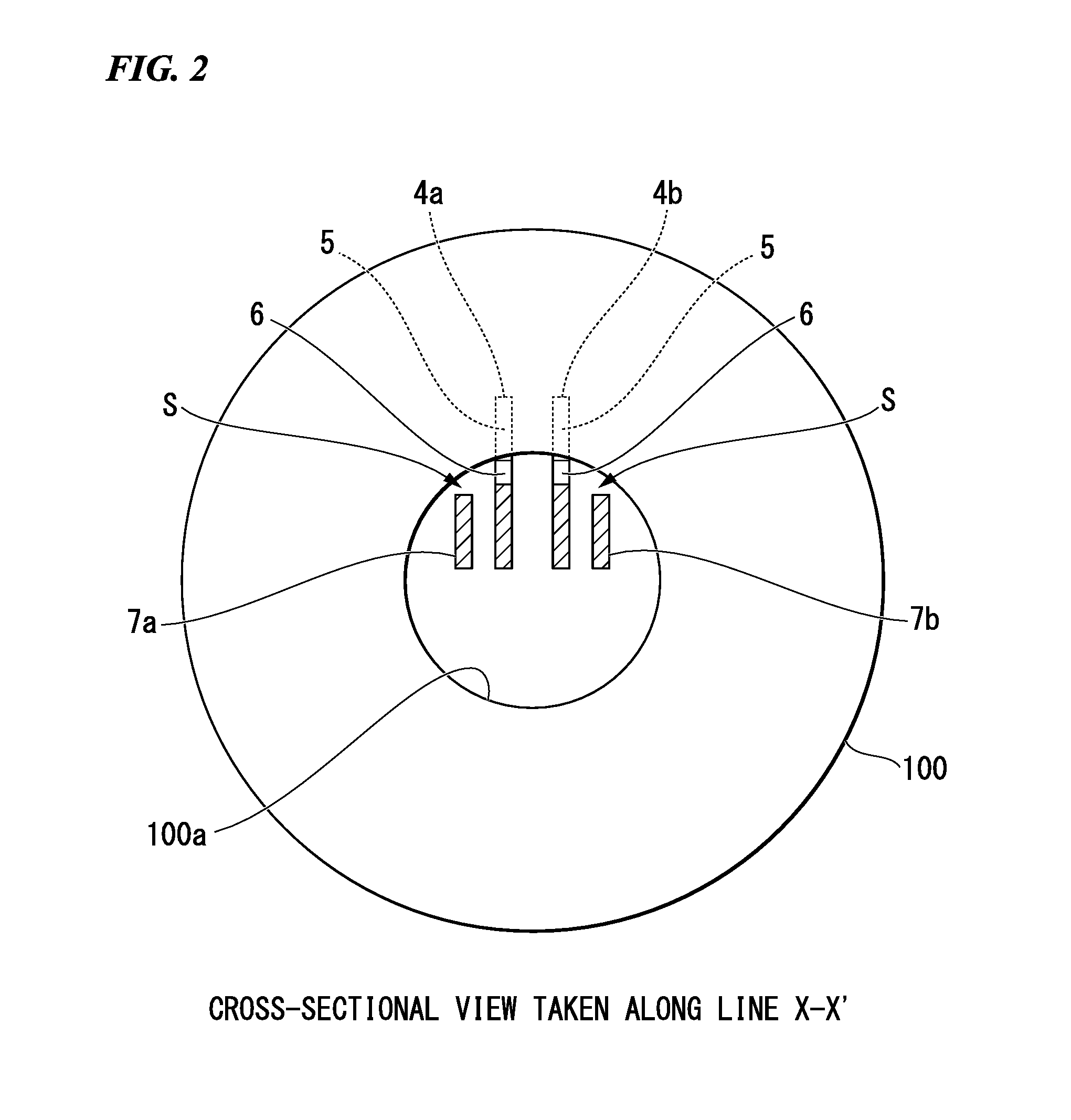
[0090]As the dipping apparatus, the same apparatus as the dipping apparatus according to the invention shown in FIGS. 1 to 4 was used. Specifically, a pair of supporting plates with a length of 200 mm, a thickness of 0.2 mm, and a height of 10 mm were arranged in parallel to each other at an interval of 5 mm, 25 magnetic recording media were arranged in V-shaped grooves formed in the pair of supporting plates at intervals of 6.35 mm, and slits with a width of 0.3 mm and a depth of 0.5 mm were provided at the contact positions between the inner circumferential portions of the magnetic recording media ...


PUM

PropertyMeasurementUnit
depthaaaaaaaaaa
widthaaaaaaaaaa
heightaaaaaaaaaa

Abstract

Provided is a magnetic recording medium manufacturing apparatus capable of forming a lubricant film with a uniform thickness on the surface of a magnetic recording medium. The magnetic recording medium manufacturing apparatus includes a hanger mechanism (2) that is inserted into a central hole (100a) of a magnetic recording medium (100) and supports the magnetic recording medium (100) in a suspended state and a lifting mechanism (3) that lifts and lowers one of the hanger mechanism (2) and the dip tank (1) relative to the other. The hanger mechanism (2) includes supporting plates (4a, 4b) that have upper ends coming into contact with an inner circumferential portion of the magnetic recording medium (100) and baffle plates (7a, 7b) that have upper ends disposed below the upper ends of the supporting plates (4a, 4b) such that a gap is formed between the upper end of the baffle plate and the inner circumferential portion of the magnetic recording medium (100) and are provided so as to face the supporting plates (4a, 4b).

Description

TECHNICAL FIELD[0001]The present invention relates to a magnetic recording medium manufacturing apparatus that dips a disk-shaped magnetic recording medium with a central hole into a dip tank filled with a liquid lubricant and draws up the magnetic recording medium from the dip tank, thereby forming a lubricant film on the surface of the magnetic recording medium.[0002]Priority is claimed on Japanese Patent Application No. 2010-025997, filed Feb. 8, 2010, the content of which is incorporated herein by reference.BACKGROUND ART[0003]In recent years, in the field of magnetic recording media used in, for example, a hard disk drive (HDD), there has been a marked increase in recording density and the recording density has increased at a high rate of about 1.5 times per year. There are various techniques for supporting the improvement in recording density. For example, one of the key technologies is controlling sliding characteristics between a magnetic head and the magnetic recording medi...

Claims


Application Information

Patent Timeline
Patent Type & Authority Patents(United States)
IPC IPC(8): B05D1/18G11B5/84
CPCG11B5/8408B05D1/18
Inventor NOGUCHI, TOMOYUKIHARA, KATSUOSAITO, MASATOKINOSHITA, YUSHI
Owner RESONAC CORPORATION
Learn More