PWM duty cycle synthesizer and method with adjustable corner frequency

a duty cycle synthesizer and corner frequency technology, applied in pulse generators, pulse manipulation, pulse techniques, etc., can solve the problems of unsuitable user, low frequency pwm signals generally are not suitable for driving electric motors, undesirable motor speed control by motor driver integrated circuits to increase too quickly or decrease too quickly, etc., to achieve the effect of much resolution

Active Publication Date: 2014-09-16
TEXAS INSTR INC
View PDF11 Cites 2 Cited by
  • Summary
  • Abstract
  • Description
  • Claims
  • Application Information

AI Technical Summary

Benefits of technology

[0015]It is another object of the invention to provide a PWM circuit which can generate a relatively high frequency PWM output signal in response to a relatively low frequency PWM input signal independently of a user's PWM control signal frequency, wherein the duty cycle of the high frequency PWM output signal is maintained precisely equal to the duty cycle of the low frequency PWM input signal.
[0016]It is another object of the invention to provide a PWM circuit which can generate a relatively high frequency PWM output signal in response to a relatively low frequency PWM input signal independently of a user-supplied PWM control signal frequency, wherein the duty cycle of the high frequency PWM output signal is programmable, is exactly equal to the duty cycle of the low frequency PWM input signal, and has at least as much resolution as the duty cycle of the low frequency PWM input signal.
[0017]It is another object of the invention to provide a PWM duty cycle synthesizer circuit which can avoid causing abrupt transfer of energy between a power supply and a PWM-controlled electric motor due to a duty cycle difference between a PWM input signal and a duty cycle of a PWM output signal generated in response to the PWM input signal.
[0018]It is an object of the invention a PWM duty cycle synthesizer circuit which can prevent the motor from abruptly causing rapid acceleration or deceleration of rotation in the motor due to duty cycle mismatch between the PWM input signal and the PWM output signal.
[0020]It is another object of the invention to provide a PWM circuit which can generate a PWM output signal having a first frequency in response to a PWM input signal having a second frequency independently of a user-supplied PWM control signal frequency, wherein the duty cycle of the PWM output signal is precisely equal to the duty cycle of the PWM input signal, and wherein the PWM circuit can be implemented in substantially less integrated circuit chip area than the closest prior art.
[0023]The algebraic summing circuit (3), the integrating circuit (5), and the PWM generator circuit (9) form a digital feedback loop which operates to equalize the duty cycle of the PWM output signal (PWMOUT) to the duty cycle of the PWM input signal (PWMIN) without loss of duty cycle resolution.

Problems solved by technology

The motor driver integrated circuit may require the motor driving PWM frequency to be a particular fixed frequency, but in some cases that may be unsuitable for the user.
However, in many cases users would like to use a low frequency PWM input signal to control the motor driver circuit, but unfortunately low frequency PWM signals generally are not suitable for driving an electric motor.
In many cases, it is undesirable for the motor speed controlled by a motor driver integrated circuit to either increase too rapidly or decrease too rapidly.
This may cause a large amount of current to be drawn from the power supply, and this may cause a sudden, large, and unacceptable decrease in the power supply voltage.
Conversely, when there is an abrupt decrease of the duty cycle, the motor typically decelerates, by strongly “braking” the rotor.
Too much energy being dumped back into the power supply may cause a large spike in power supply voltage (e.g., from 5 volts to 10 volts), which could damage other circuits / devices in the system.

Method used


Image

  • PWM duty cycle synthesizer and method with adjustable corner frequency
  • PWM duty cycle synthesizer and method with adjustable corner frequency
  • PWM duty cycle synthesizer and method with adjustable corner frequency

Examples


Embodiment Construction

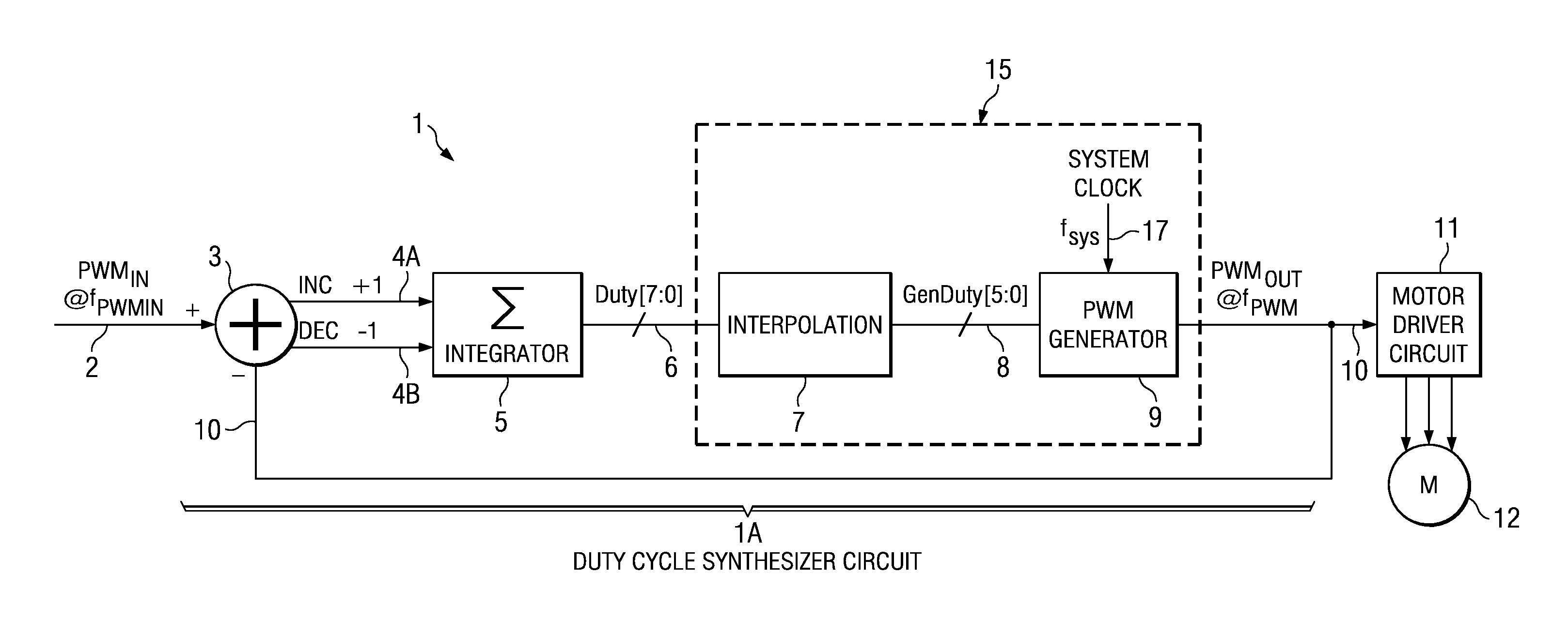
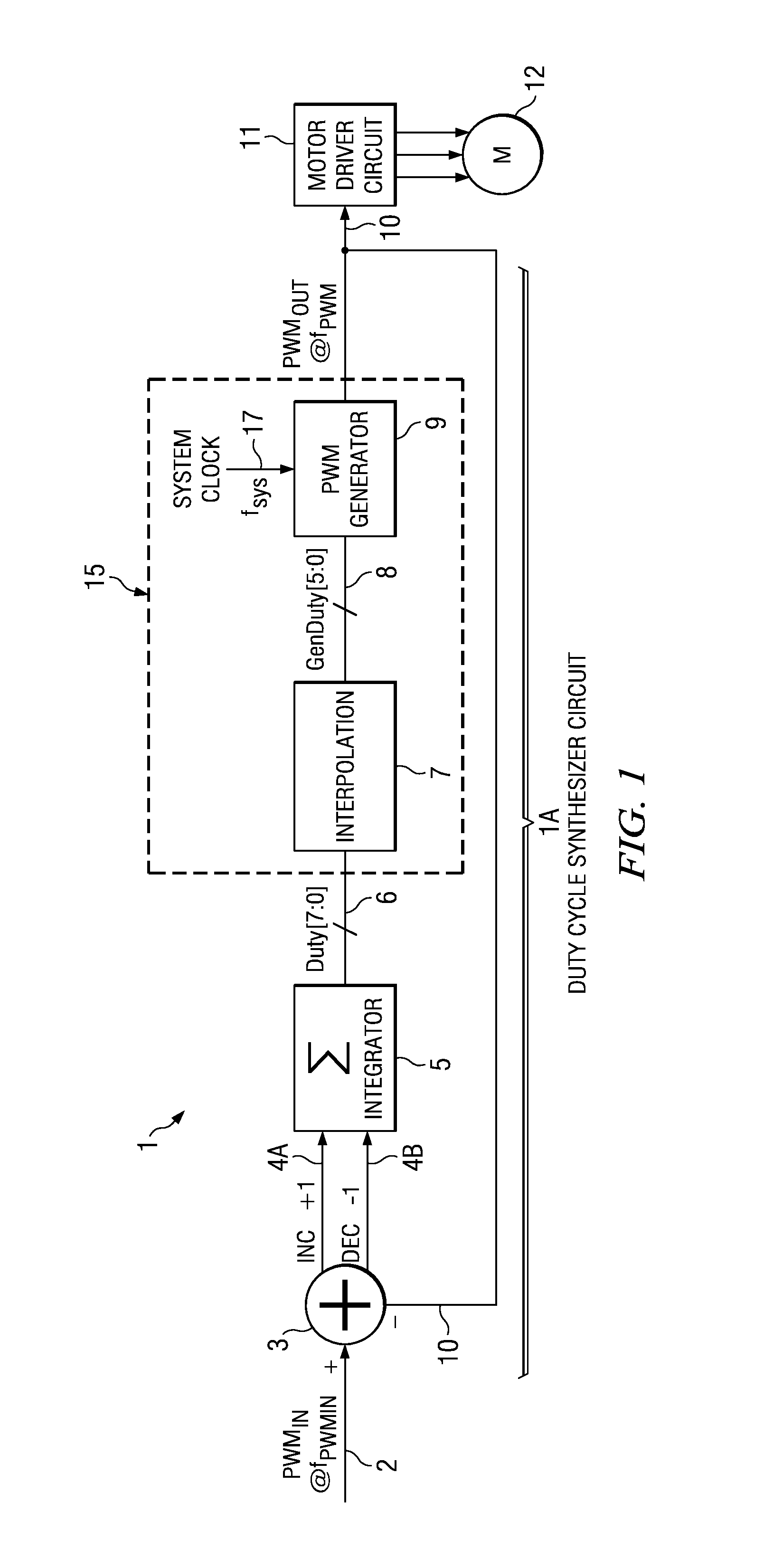
[0041]The invention provides a PWM control circuit including a duty cycle synthesizer circuit which controls the frequency of a PWM output signal (such as a PWM signal driving an electric motor) independently of the frequency of a user-supplied input PWM input signal. Any duty cycle differences between the PWM input signal and the PWM output signal are, in effect, filtered or smoothed sufficiently to prevent excessively rapid acceleration or rapid deceleration in the motor so as to avoid any large, fast energy exchange between a power supply and the motor controlled by the PWM control circuit.

[0042]FIG. 1 shows a block diagram of a PWM control circuit 1 which is capable of producing a PWM output signal PWMOUT having a frequency fPWM that is substantially independent of a user-supplied PWM input signal PWMIN having a frequency fPWMIN. PWM control circuit 1 includes a digital duty cycle synthesizer circuit 1A which includes a signal comparison circuit or “delta” circuit 3, an integrat...


PUM


Abstract

A circuit is provided that includes summing circuit for comparing the PWM output signal to the PWM input signal and producing an increment signal if a value of the PWM input signal exceeds a corresponding value of the PWM output signal and producing a decrement signal if a value of the PWM input signal is less than a corresponding value of the PWM output signal. An integrator produces a duty cycle signal by producing an increase in value of the duty cycle signal in response to each increment signal and a decrease in value of the duty cycle signal in response to each decrement signal. A PWM generator produces the PWM output signal in response to the duty cycle signal to cause the duty cycle of the PWM output signal to equal the duty cycle of the PWM input signal with no loss of duty cycle resolution.

Description

BACKGROUND OF THE INVENTION[0001]The present invention relates generally to PWM (pulse width modulation) circuits which generate a PWM output signal in response to an PWM input signal, and more particularly to such PWM circuits which generate a PWM output signal having a fixed frequency and a duty cycle that is the same as the duty cycle of the PWM input signal.[0002]PWM circuits are widely used as control circuits, especially in electric motor driving applications. PWM output signals typically are generated by means of digital circuitry and associated system clock signals or by means of analog comparator circuitry. For a typical brushless DC (BLDC) motor controller, the system clock fsys ranges from roughly 1 MHz to 10 MHz, and the expected output PWM frequency fPWM ranges from roughly 20 kHz to 200 kHz, depending on the specific application.[0003]One prior art PWM motor driving circuit includes a specially designed PWM generator, an output multiplexer (MUX), and an interpolator to...

Claims


Application Information

Patent Timeline
Patent Type & Authority Patents(United States)
IPC IPC(8): H03K5/04
CPCH03K7/08
Inventor ZHANG, RUOCHENLU, YISONGTAN, PAUY GUAN
Owner TEXAS INSTR INC
Why Eureka
Try Eureka