
Systems and methods for suppressing coherent structured illumination artifacts

a technology of coherent structure and artifacts, applied in the field of systems and methods for suppressing coherent structure illumination artifacts, can solve problems such as errors in detected signals and unwanted artifacts, and achieve the effects of reducing errors, high-speed, power-efficient and light-efficient pattern projection and imaging

Inactive Publication Date: 2014-09-30
FELDKHUN DANIEL
View PDF19 Cites 7 Cited by
  • Summary
  • Abstract
  • Description
  • Claims
  • Application Information

AI Technical Summary

Benefits of technology

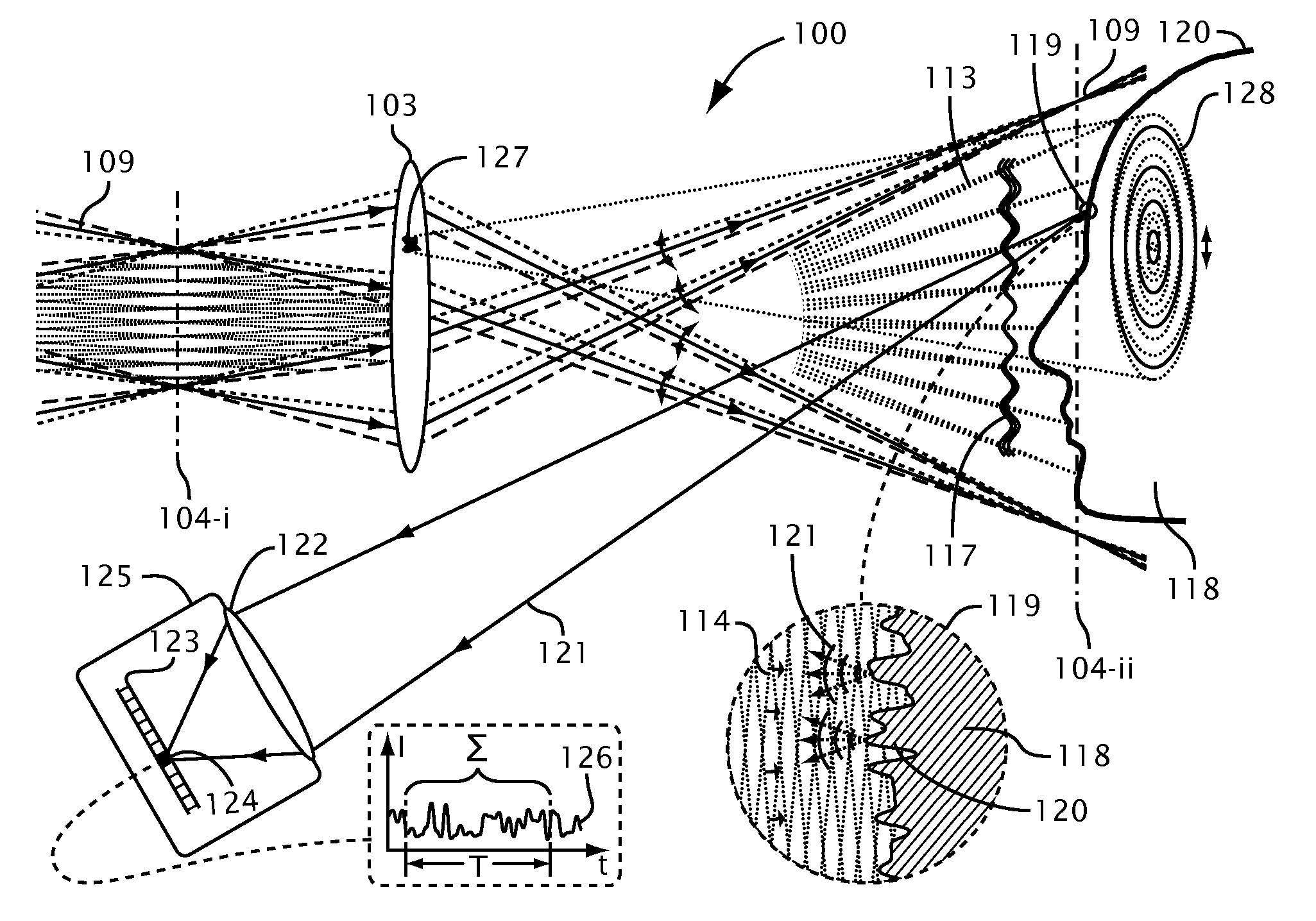
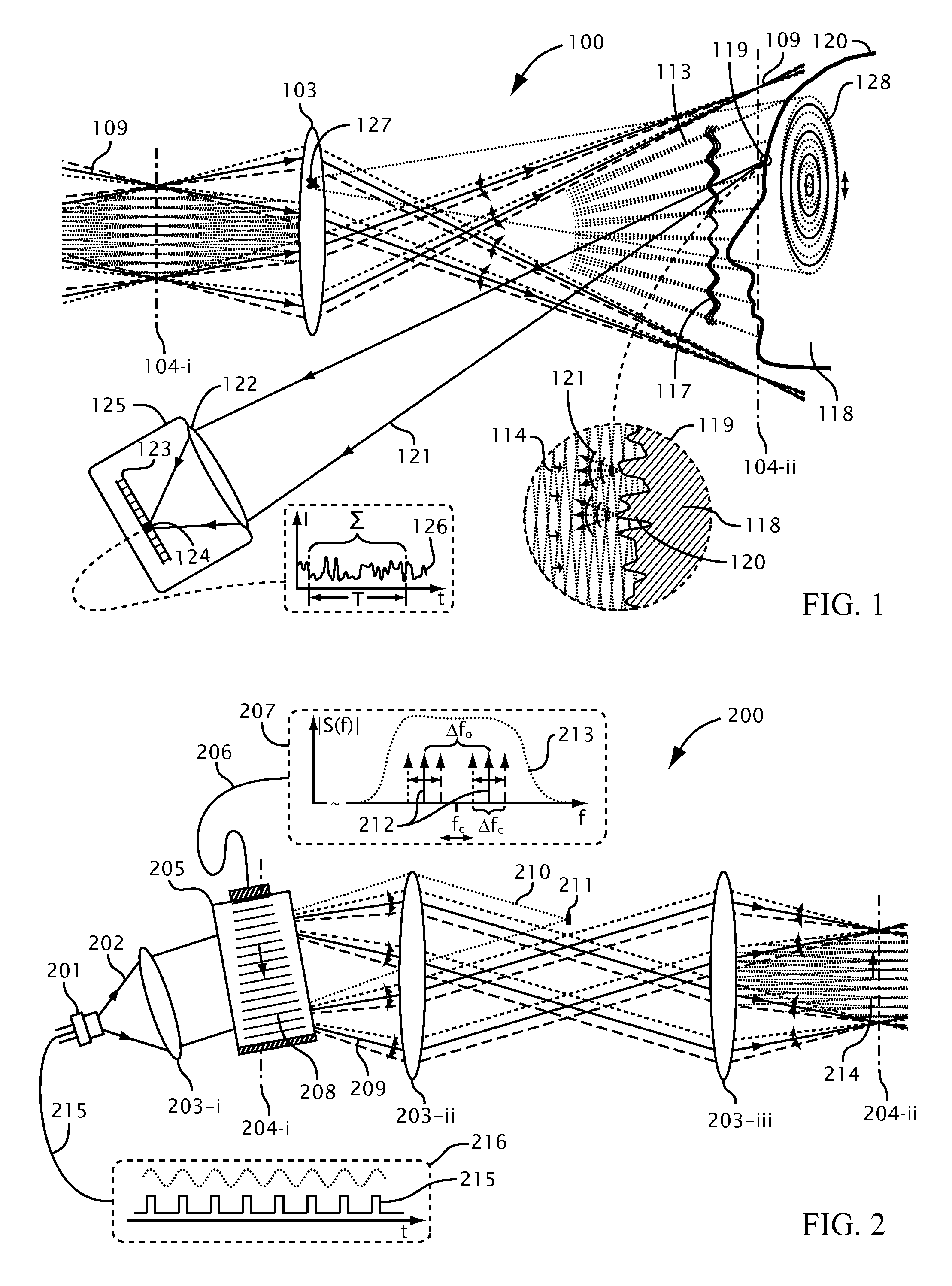
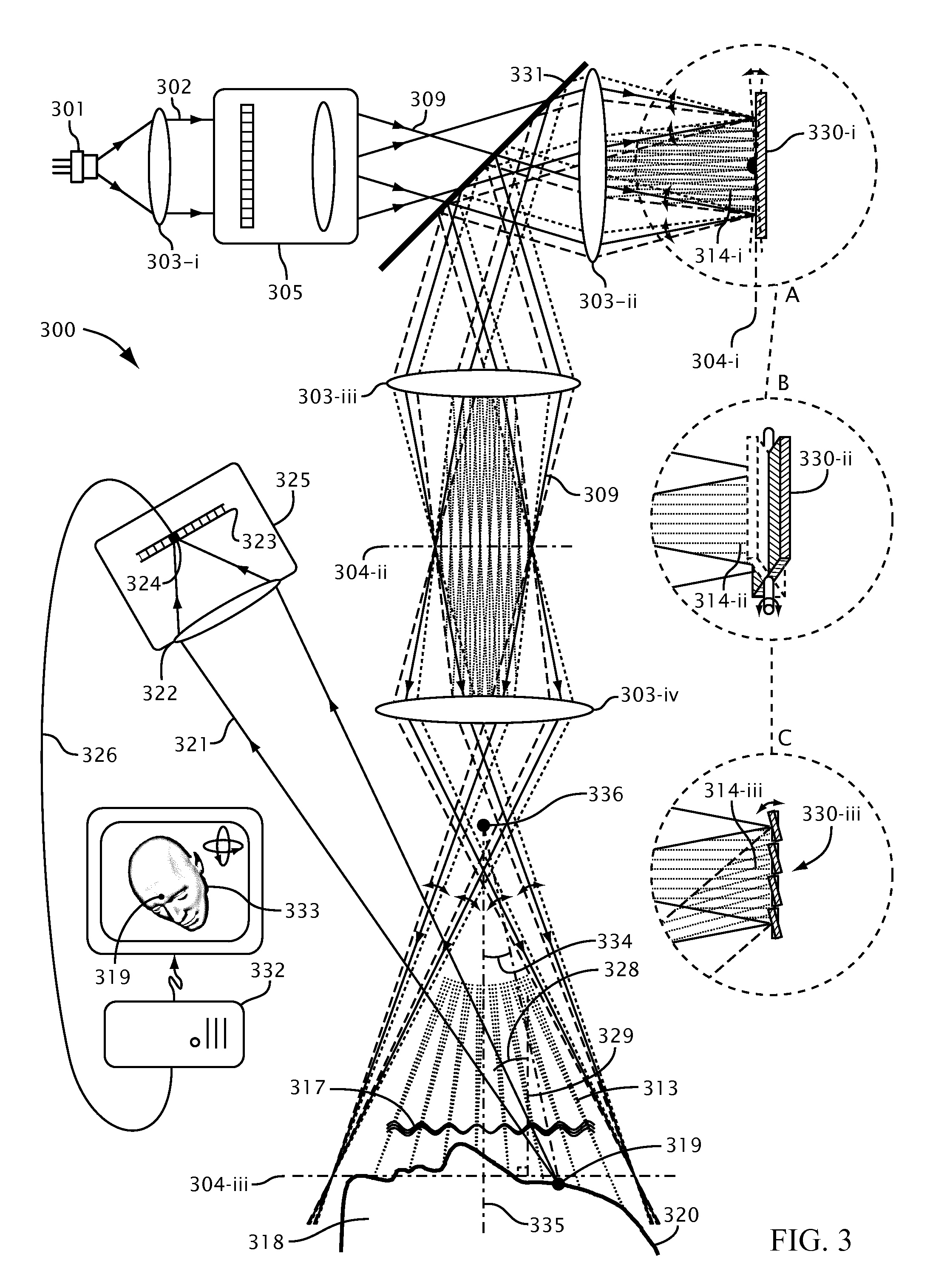
The patent text describes methods and systems for reducing coherent artifacts in laser-based pattern projection and detection systems. These methods and systems may use an acousto-optic device or another spatial light modulator to modulate the laser illumination and suppress coherent artifacts. This may allow for flexible and efficient suppression without compromising the depth of field of the system. Additionally, the patent text describes methods and systems for generating and controlling interference patterns and suppressing coherent artifacts using a single acousto-optic device. These techniques may reduce errors due to coherent artifacts in laser-based three-dimensional imaging systems and enable high-speed, power-efficient, and light-efficient pattern projection and imaging.

Problems solved by technology

High temporal and spatial coherence of laser illumination may result in unwanted artifacts and errors in a detected signal.
Speckle may occur at the focal plane of an imaging lens or in free space in the near or far field of the illuminated object, and may be a dominant source of error in a laser-based illumination and detection system.

Method used


Image

  • Systems and methods for suppressing coherent structured illumination artifacts
  • Systems and methods for suppressing coherent structured illumination artifacts
  • Systems and methods for suppressing coherent structured illumination artifacts

Examples


Embodiment Construction

[0010]This description provides example embodiments only, and is not intended to limit the scope, applicability, or configuration of the disclosed technology. Rather, the ensuing description of the embodiments will provide those skilled in the art with an enabling description for implementing embodiments of the disclosed technology. Various changes may be made in the function and arrangement of elements without departing from the spirit and scope of the disclosed technology.

[0011]Thus, various embodiments may omit, substitute, or add various procedures or components as appropriate. For instance, it should be appreciated that in alternative embodiments, the methods may be performed in an order different from that described, and that various steps may be added, omitted, or combined. Also, features described with respect to certain embodiments may be combined in various other embodiments. Different aspects and elements of the embodiments may be combined in a similar manner.

[0012]It sho...


PUM


Abstract

Methods and systems are provided for suppressing speckle and / or diffraction artifacts in coherent structured illumination sensing systems. A coherent radiation pattern forms an interference pattern at an illumination image plane and illuminates an object. Radiation scattered or otherwise emitted by the object is detected to produce a signal, which is integrated in time. Coherent artifact suppression is attained by using a spatial modulator, such as an acousto-optic device, to vary a phase gradient at the illumination image plane during the signal integration time. Various embodiments are provided for purposes including without limitation: preserving the depth of field of the coherent illumination; using the same acousto-optic device for pattern generation and coherent artifact suppression; electronically controlling the effective spatial coherence of the illumination system; and reducing errors due to coherent artifacts in a laser-based three dimensional imaging system.

Description

CROSS-REFERENCES TO RELATED APPLICATIONS[0001]This application is a non-provisional of, and claims the benefit of, U.S. Provisional Patent Application Ser. No. 61 / 543,784, entitled “SYSTEMS AND METHODS FOR REDUCING SPECKLE AND OTHER COHERENT ARTIFACTS,” filed Oct. 5, 2011, the entire disclosure of which is incorporated herein by reference for all purposes.BACKGROUND[0002]High temporal and spatial coherence of laser illumination may result in unwanted artifacts and errors in a detected signal. For example, pixel edges, coating blemishes, or specks of dust on a lens in a coherent optical system may produce diffraction patterns on an illuminated object, modulating or sometimes even obscuring a desired illumination pattern and thereby producing detected signal errors, herein referred to as diffraction artifacts. Moreover, microscopic roughness on the illuminated object may produce a diffraction pattern of its own leading to spatial intensity fluctuations at the detector, herein referred...

Claims


Application Information

Patent Timeline
Patent Type & Authority Patents(United States)
IPC IPC(8): G01B11/02G01B9/02G01B11/25G01B21/04G02B21/00G02B27/00G02B27/48
CPCG02B27/0025G01B11/25G02B21/004G01B21/045G02B27/48G01B9/02082G01B11/2441G01B9/02041
Inventor FELDKHUN, DANIEL
Owner FELDKHUN DANIEL
Learn More