Thermal energy storage system

a technology of thermal energy storage and energy storage unit, which is applied in the direction of solar heat storage, lighting and heating equipment, and greenhouse gas reduction to achieve the effect of increasing the efficiency of the thermal storage unit and low cos

Inactive Publication Date: 2014-10-07
KAPTEYN KELVIN L
View PDF47 Cites 15 Cited by
  • Summary
  • Abstract
  • Description
  • Claims
  • Application Information

AI Technical Summary

Benefits of technology

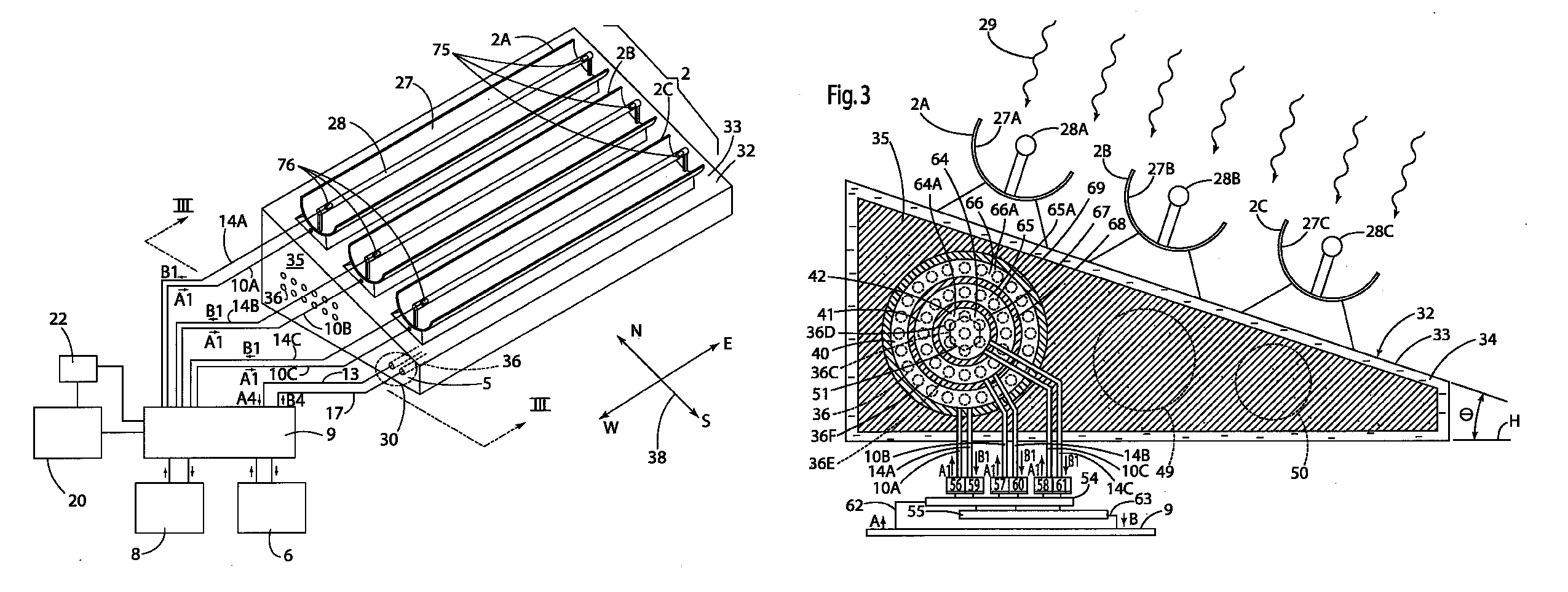
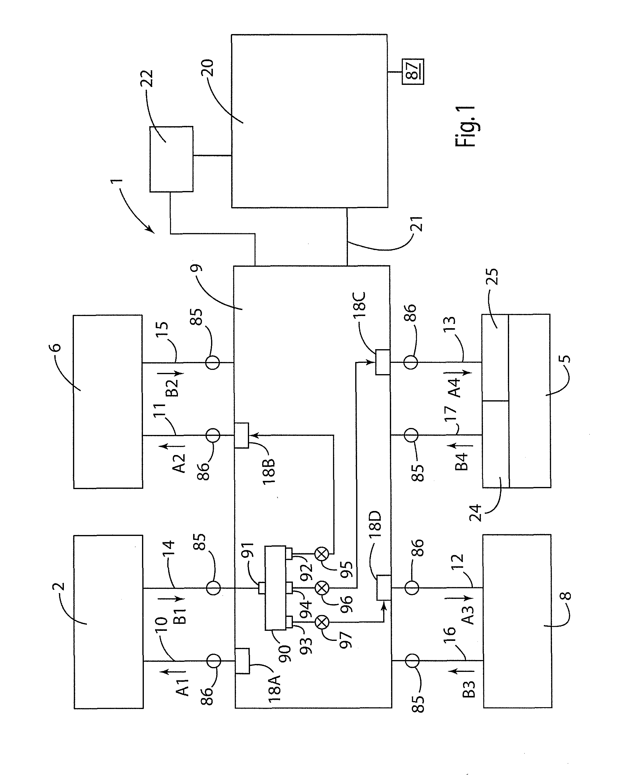
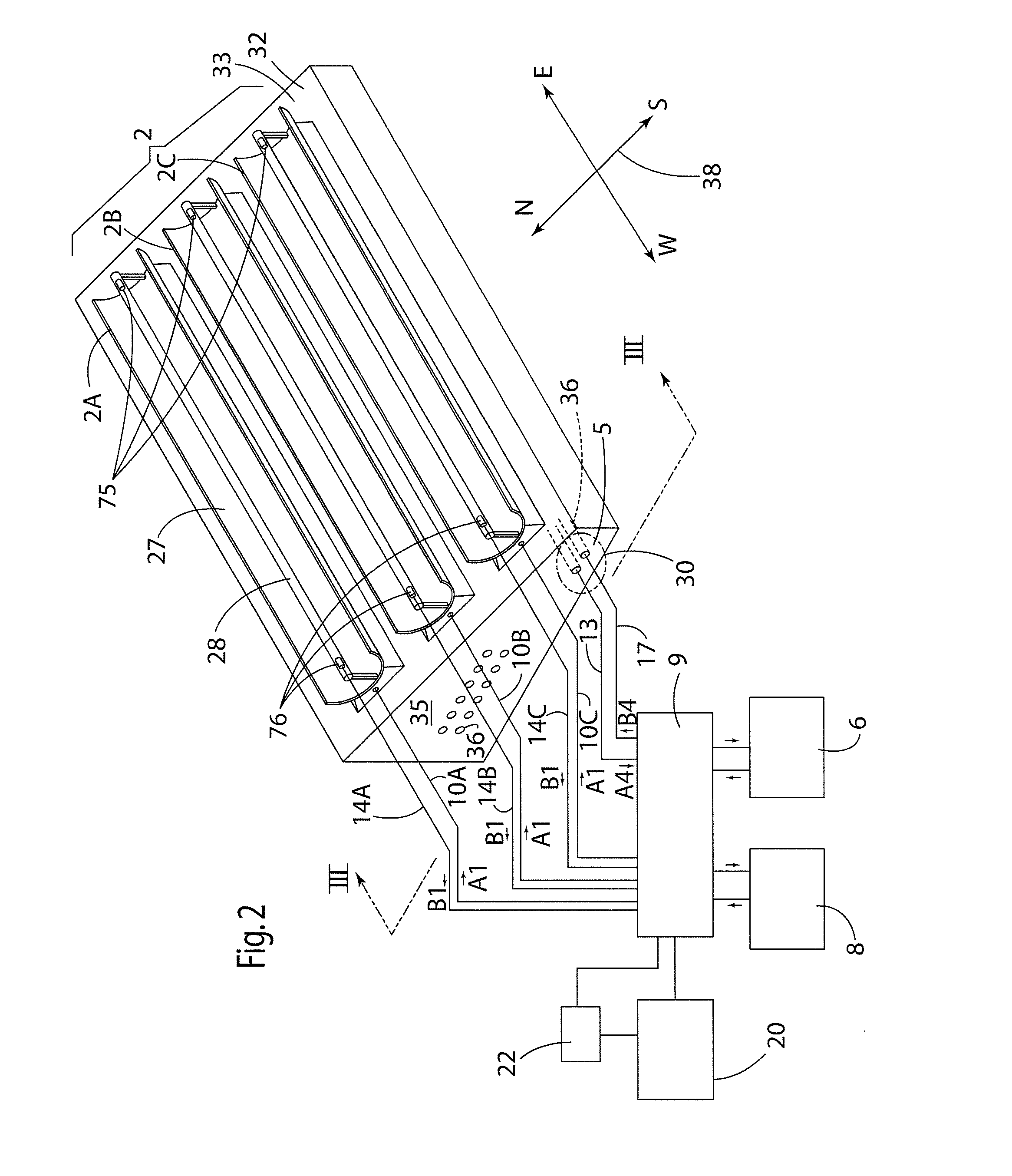
[0005]One aspect of the present invention is a thermal energy system including at least one source of thermal energy providing heated oil or other fluid at a first temperature that is substantially greater than an ambient air temperature. The thermal energy system also includes at least one energy-consuming unit/facility that consumes the thermal energy transported to it by the heated oil or other fluid. The system further includes at least one thermal energy storage unit or facility having a thermal mass that selectively receives and releases thermal energy that is transported to and from the thermal mass by the oil or other fluid. A fluid conduit system fluidly interconnects the source of thermal energy, the energy-consuming unit/facility and the thermal energy storage unit. The fluid conduit system fluidly interconnects the source of thermal energy, the energy-consuming unit/facility, and the thermal energy storage unit. The thermal energy control system also includes a control system configured to control flow of fluid through the fluid conduit system according to predefined criteria. The one thermal energy storage unit may include a waterproof barrier defining an interior space, and includes substantially loose solid material disposed in the interior space. At least one fluid conduit extends through the loose solid material to transfer thermal energy from oil flowing through the fluid conduit to the

Problems solved by technology

The system may include an auxiliary or backup heat source that utilizes combustion or other processes to generate heat from fuel during times in which the so

Method used


Image

  • Thermal energy storage system
  • Thermal energy storage system
  • Thermal energy storage system

Examples


Embodiment Construction

[0013]For purposes of description herein, the terms “upper,”“lower,”“right,”“left,”“rear,”“front,”“vertical,”“horizontal,” and derivatives thereof shall relate to the invention as oriented in FIG. 3. However, it is to be understood that the invention may assume various alternative orientations and step sequences, except where expressly specified to the contrary. It is also to be understood that the specific devices and processes illustrated in the attached drawings and described in the following specification are simply exemplary embodiments of the inventive concepts defined in the appended claims. Hence, specific dimensions and other physical characteristics relating to the embodiments disclosed herein are not to be considered as limiting, unless the claims expressly state otherwise.

[0014]With reference to FIG. 1, an energy production, storage, and utilization system 1 includes a source of thermal energy such as one or more solar collectors 2 that collect thermal energy from the su...


PUM


Abstract

A thermal energy storage system includes fluid conduits disposed in a loose solid material. The loose solid material may be disposed inside a waterproof barrier, and the fluid conduits may be configured to define a plurality of zones having different temperatures in operation. The system may include a solar collector or other source of heated oil or other fluid that is routed to the thermal energy storage unit and/or an energy-consuming facility.

Description

BACKGROUND OF THE INVENTION[0001]Various types of systems for heating and / or cooling various facilities have been developed. One type of system utilizes heat collected from natural sources or excess heat produced as a byproduct of other processes. Such systems typically include a heat source such as solar collectors, a heat-using facility, and a thermal storage unit. The thermal storage unit can be utilized to compensate for time differences between peak thermal energy generation and thermal energy use requirements. For example, if solar energy is being utilized to heat buildings or the like, solar collectors may be utilized to collect heat. However, such collectors typically collect the most thermal energy during the day, whereas a building may need to be heated at night when the ambient air is colder. The thermal storage unit stores excess energy collected during periods of time during which thermal energy collection exceeds thermal energy use, and the stored thermal energy is dra...

Claims


Application Information

Patent Timeline
IPC IPC(8): F24J2/34
CPCF24J2/34Y02E60/142F28D20/0056F28D2020/0078F28D20/0034F24J2/14Y02E10/45Y02E70/30F24S23/74F24S60/00Y02E10/40Y02E60/14
Inventor KAPTEYN, KELVIN, L.
Owner KAPTEYN KELVIN L
Why Eureka
Try Eureka