Plug-in wire connection terminal structure

a terminal structure and plug-in wire technology, applied in the direction of coupling contact members, coupling device connections, contact members penetrating/cutting insulation/cable strands, etc., can solve the problems of increasing the difficulty of forming and processing pin-shaped socket members, insufficient holding force, and failure to meet the economic efficiency principle, etc., to achieve easy assembly, reduce the development and assembly cost of the plug-in wire connection terminal structure, and simplify the structure

Active Publication Date: 2014-10-07
SWITCHLAB SHANGHAI +1
View PDF4 Cites 20 Cited by
  • Summary
  • Abstract
  • Description
  • Claims
  • Application Information

AI Technical Summary

Benefits of technology

[0017]It is therefore a primary object of the present invention to provide a plug-in wire connection terminal structure, which has simplified structure and is easy to assemble. Therefore, the development and assembling cost for the plug-in wire connection terminal structure is lowered.
[0018]It is a further object of the present invention to provide the above plug-in wire connection terminal structure, in which the components are easy to process and only little waste material is produced during the processing procedure. Therefore, the processing and material cost is lowered.
[0019]It is still a further object of the present invention to provide the above plug-in wire connection terminal structure, which can provide better and more stable elastic holding effect to keep the terminal structure in good contact with another terminal mated with the terminal structure.

Problems solved by technology

This fails to meet the principle of economic efficiency.
This will increase difficulty in forming and processing the pin-shaped socket member (or the female terminal).
Otherwise, in the case of unfitness, the holding force will be insufficient (the size of the inner circumference of the spring steel collar or the outer housing is too large) or the elastic expansion of the pin-shaped socket member or female terminal is insufficient (the size of the inner circumference of the spring steel collar or the outer housing is too small).
Such requirement in dimension precision will also cause increase of manufacturing cost.3. The spring steel collar (or the outer housing) is a partially split structure with a C-shaped cross section.
However, such spring steel collar (or the outer housing) will inevitably have poorer elasticity so that the holding force applied to the pin-shaped socket member (or the female terminal) is easy to deteriorate.
However, under such circumstance, it will be uneasy to assemble the spring steel collar (or the outer housing) on the annular recess (or annular groove).
Accordingly, in consideration of structural design, it is hard to decide whether the difficulty in assembling should be lowered or the holding force should be increased.

Method used


Image

  • Plug-in wire connection terminal structure
  • Plug-in wire connection terminal structure
  • Plug-in wire connection terminal structure

Examples


Embodiment Construction

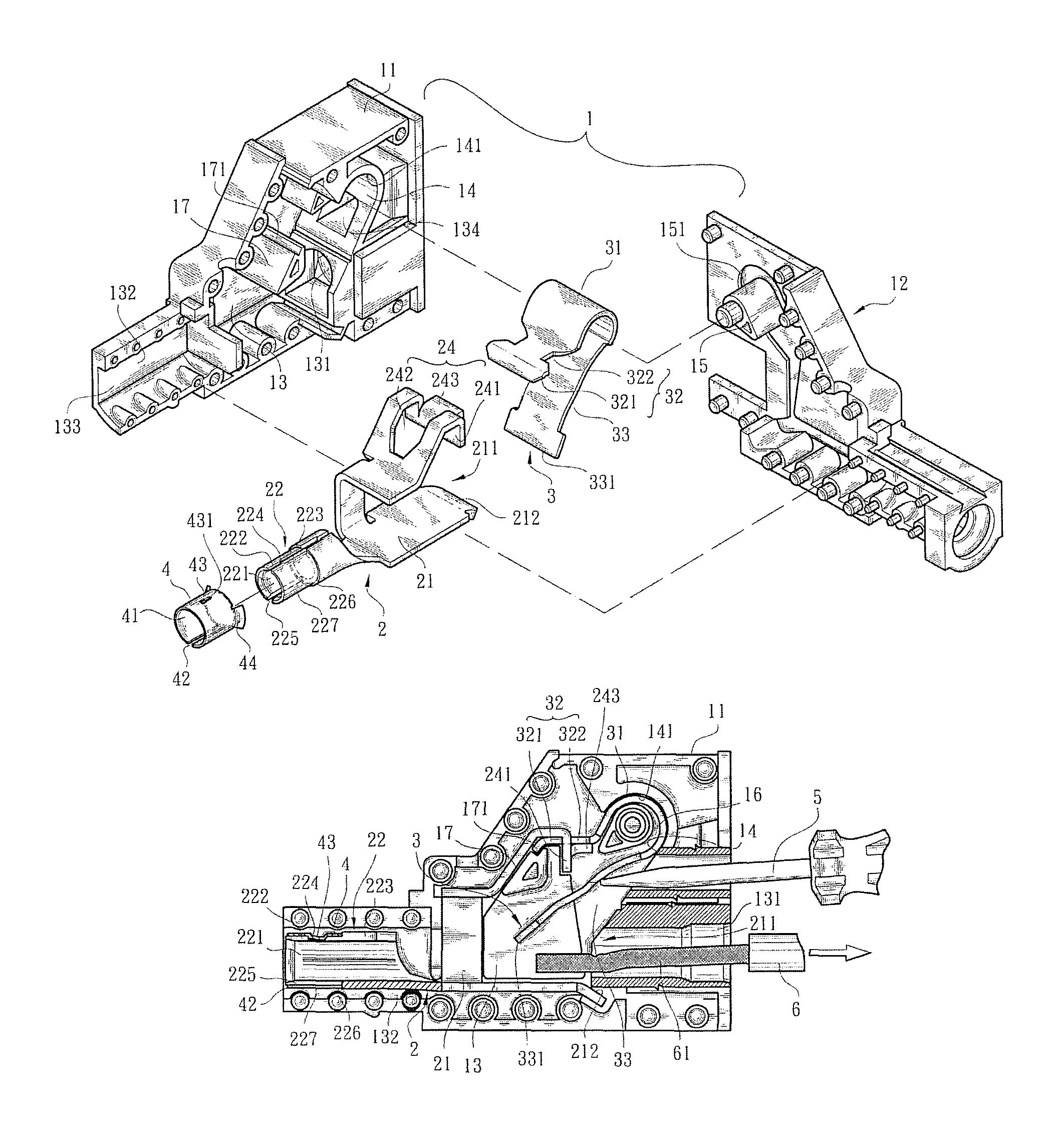
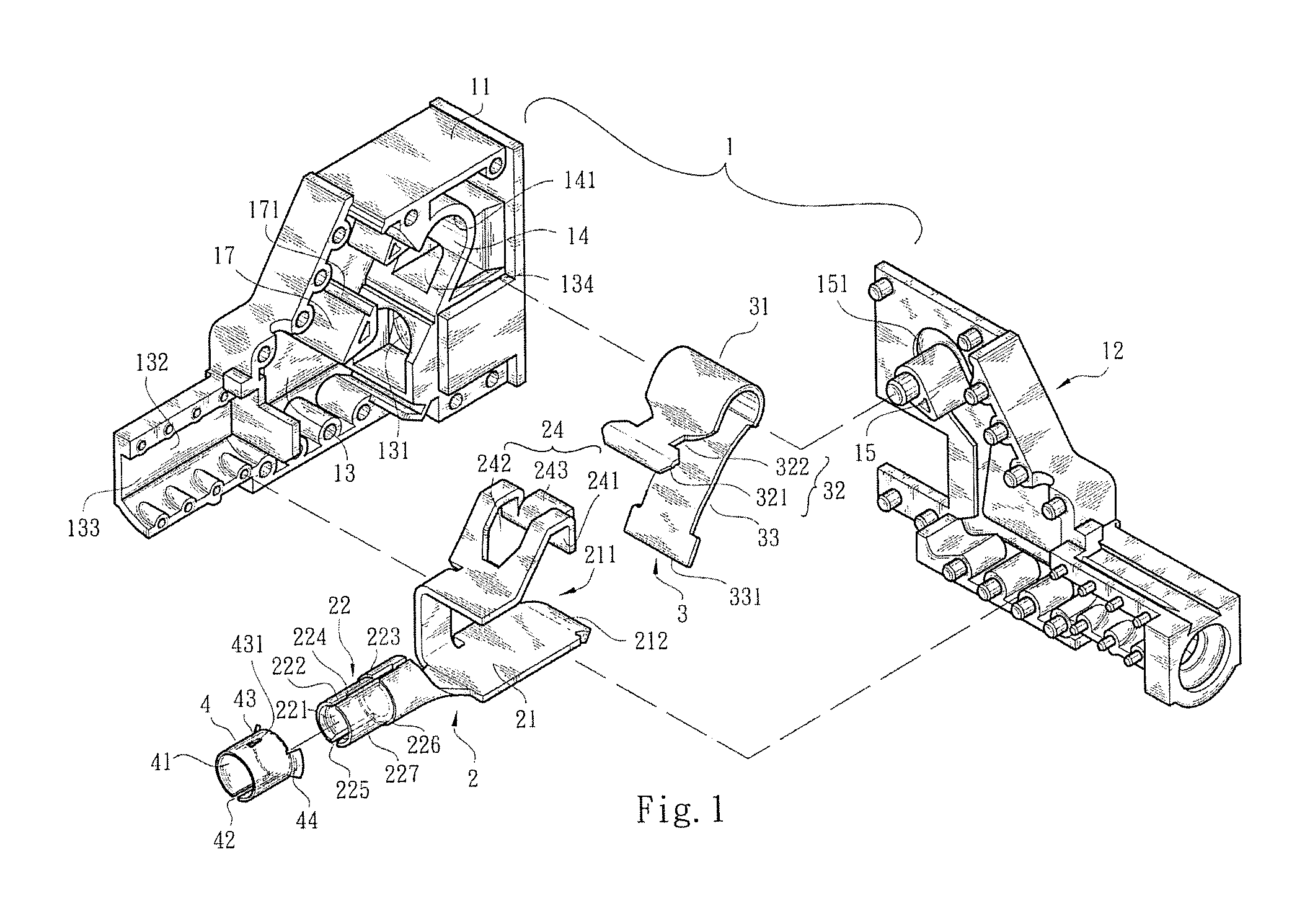
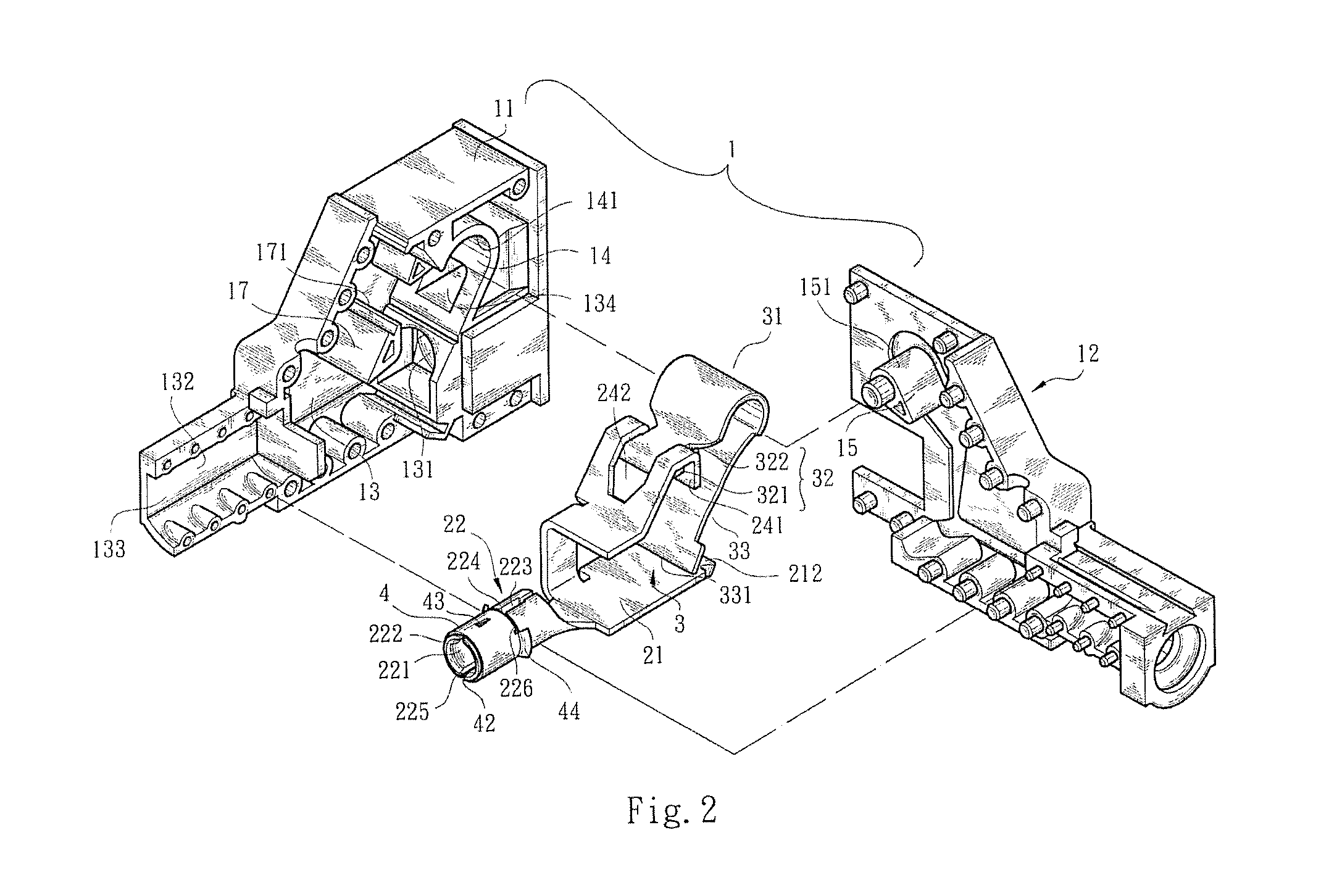
[0031]Please refer to FIGS. 1 to 5. The plug-in wire connection terminal structure of the present invention includes a main body 1, a holding plate 2, a leaf spring 3 and a collar member 4. The main body 1 is composed of an insulation casing 11 and an insulation cover 12 mated with the insulation casing 11. The insulation casing 11 has an internal receiving space 13. The lateral sides of the receiving space 13 are respectively formed with a wire inlet 131 in communication with outer side, a channel 132 and a side section 14 having an arched inner face 141. The channel 132 communicates with the outer side via an opening 133. A stopper block 17 is disposed between the side section 14 and the receiving space 13. One side of the stopper block 17, which side faces the side section 14, is recessed to form a locating section 171. In addition, a shift perforation 134 in communication with the outer side is disposed between the side section 14 and the wire inlet 131. A middle protrusion bloc...


PUM


Abstract

A plug-in wire connection terminal structure includes a main body having a receiving space. A lateral side of the receiving space is formed with an arched guide slot. A holding plate has a receiving section formed with a wire entrance and a conductive contact section formed with a socket. An annular wall of the socket is formed a slit. A small-diameter fitting section is disposed at an outer end of the conductive contact section. A collar member is tightly fitted on the fitting section. A connection section is disposed on the receiving section. A leaf spring has a bight section received in the arched guide slot. One end of the leaf spring is formed with a connected section latched with the connection section. The other end of the leaf spring is formed with an abutment end obliquely extending the receiving section.

Description

BACKGROUND OF THE INVENTION[0001]1. Field of the Invention[0002]The present invention relates generally to a plug-in wire connection terminal structure, and more particularly to a plug-in wire connection terminal structure, which has simplified structure and is easy to assemble. Moreover, the plug-in wire connection terminal structure has excellent structural strength and is able to provide excellent elastic holding effect.[0003]2. Description of the Related Art[0004]There are various conventional large-current connectors. For example, Chinese Invention Patent Publication No, CN 101595603A discloses an electrical wire connection terminal. The terminal has an insulation housing, a metal piece disposed in the housing and a leaf spring disposed in the housing. The metal piece is made of high-conductivity metal material and the leaf spring has highly stable elasticity. The metal piece is assembled with the leaf spring to forma conduction circuit for conducting large current. The metal p...

Claims


Application Information

Patent Timeline
Patent Type & Authority Patents(United States)
IPC IPC(8): H01R11/20
CPCH01R4/4827H01R13/18H01R9/16H01R13/111H01R4/48275
Inventor WU, CHIH-YUANLIEN, MING-HUNG
Owner SWITCHLAB SHANGHAI
Why Eureka
Try Eureka