Combination of outer motor and control box therefor

a technology of control box and outer motor, which is applied in the direction of structural association, supports/enclosements/casings, dynamo-electric machines, etc., can solve the problems of high failure rate, achieve reasonable and orderly wiring installation, prolong service life, and simple and cost-effective production process

Active Publication Date: 2014-10-07
ZHONGSHAN BROAD OCEAN
View PDF7 Cites 4 Cited by
  • Summary
  • Abstract
  • Description
  • Claims
  • Application Information

AI Technical Summary

Benefits of technology

[0006]In view of the above-described problems, it is one objective of the invention to provide a combination of an outer motor and a control box therefor in which a control box is employed as a rear end cover of a main body, a fairlead arranged on the edge of an inner wall of the control box extends through the bottom of a motor casing to connect the empty cavity. Such combination has the following advantages: it is better integrated with a reasonable and orderly wiring installation; the motor lead wire can be easily connected; the control circuit board is enclosed in the control box and located at an upper side of the control box, thus it is unlikely to be soaked by water and the motor has more stable performance and long service life.
[0014]Advantages of the invention are summarized below: 1) the control box is sheathed in the tail end of the casing, the upper bottom surface center of the control box is arranged with the bearing chamber corresponding to that arranged at the front end cover and providing support for the rotor assembly via the bearing, the control box forms the cavity downwards accommodating the control circuit board, the cover is mounted at the bottom of the control box, the fairlead arranged at inner wall of the control box extends through the bottom surface of the motor casing to connect the empty cavity, the connecting wire connecting the motor and the controller extends through the fairlead and all motor lead wires extend out of the control box. Such structure has a reasonable and orderly wiring installation with simple and cost-effective production process, thus the motor will be more competitive; 2) the fairlead is in pairs with one for a power line and the other one for a signal line, the fairlead has a length smaller than a height of the side wall of the control box and it is spaced apart from the cover. The water entering the inner motor will be firstly guided to the control box through the fairlead and then discharged from the water outlet arranged at the control box. In this way, the control circuit board mounted at upper side of the fairlead is unlikely to be soaked in water, thereby prolonging its service life; and 3) the bottom surface separates the empty cavity inside the motor casing from the cavity of the control box, and thus such structure is more compact and integrated.

Problems solved by technology

Thus, the structure has the following disadvantages: 1) the controller is independent from the rear end cover, thus it is complicated and costly to make; 2) the main body and the controller are respectively connected with lead wires and thus the electrical connection is complex and liable to cause fault; and 3) the control box has no capacity of water discharge, and thus it is easy to be soaked by water, thereby leading to a high failure rate.

Method used


Image

  • Combination of outer motor and control box therefor
  • Combination of outer motor and control box therefor
  • Combination of outer motor and control box therefor

Examples


Embodiment Construction

[0022]For further illustrating the invention, experiments detailing combination of an outer motor and a control box therefor are described below. It should be noted that the following examples are intended to describe and not to limit the invention.

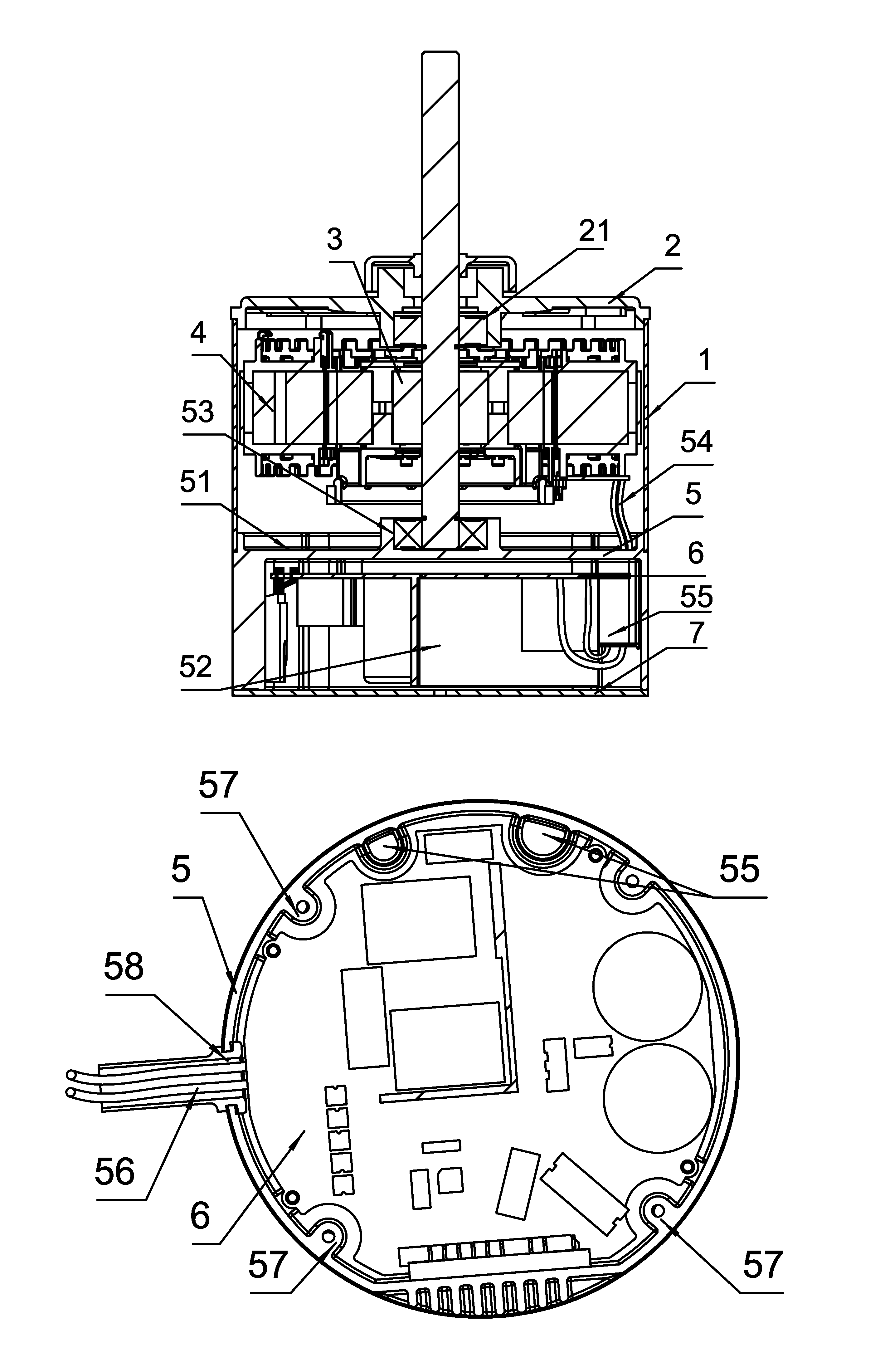
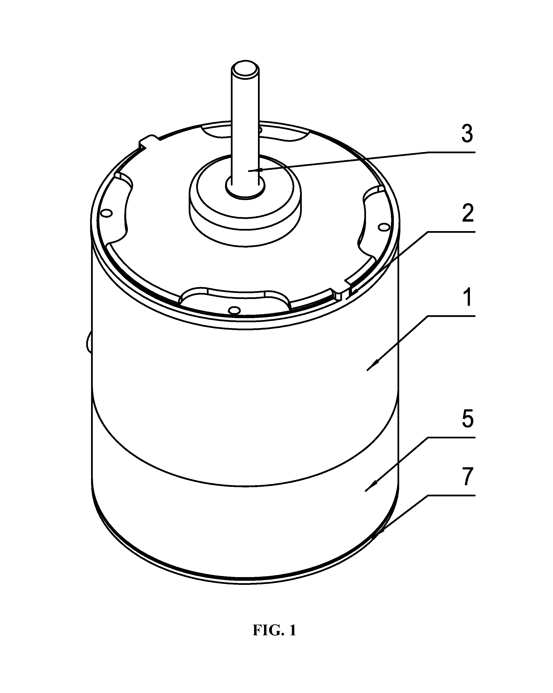
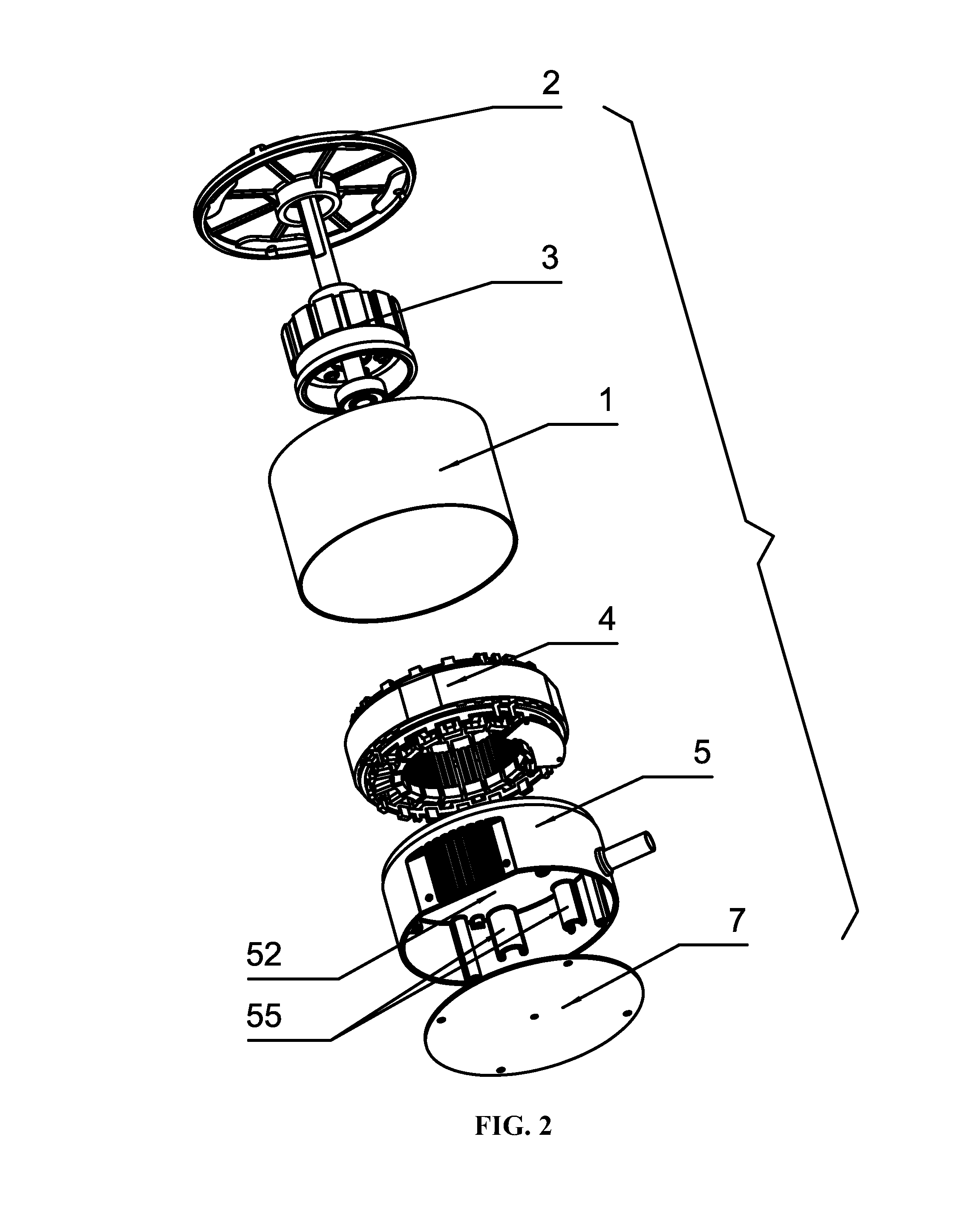
[0023]As shown in FIGS. 1-7, combination of an outer motor and a control box therefor comprises an upper main body and a lower controller. The upper main body comprises a casing 1, a front end cover 2, a rotor assembly 3, and a stator assembly 4. The rotor assembly 3 and the stator assembly 4 are mounted inside the casing 1 and the front end cover 2 is mounted at the upper end of the casing 1. The controller comprises a control box 5 and a control circuit board 6. The control box 5 is sheathed in a tail end of the casing 1. A center of an upper bottom surface 51 of the control box 5 is arranged with a bearing chamber 53 corresponding to a bearing chamber 21 arranged at the front end cover 2 and providing support for the rotor assembly 3 v...


PUM


Abstract

A combination of an outer motor and a control box therefor including an upper main body and a lower controller. The upper main body includes a casing, a front end cover, a rotor assembly, and a stator assembly. The controller includes a control box and a control circuit board, and the control box is sheathed in a tail end of the casing. A center of an upper bottom surface of the control box is arranged with a bearing chamber corresponding to that arranged at the front end cover. The control box forms a cavity downwards accommodating the control circuit board. A cover is mounted at the bottom of the control box. A fairlead arranged at an inner wall of the control box extends through the bottom of the motor casing to connect an empty cavity of the casing.

Description

CROSS-REFERENCE TO RELATED APPLICATIONS[0001]Pursuant to 35 U.S.C. §119 and the Paris Convention Treaty, this application claims the benefit of Chinese Patent Application No. 201020600663.4 filed Nov. 02, 2010, the contents of which are incorporated herein by reference.BACKGROUND OF THE INVENTION[0002]1. Field of the Invention[0003]The invention relates to a combination of an outer motor and a control box therefor.[0004]2. Description of the Related Art[0005]A conventional brushless DC motor is composed of a main body and a controller having a control box, in which the main body includes a front end cover, a rotor, a stator, a casing, and a rear end cover while the controller itself is an aluminum casting piece directly mounted at the rear end cover of the main body. The control box includes a circuit board, on which electronic components are mounted. An empty cavity inside the motor casing is separated from a cavity of the control box. Thus, the structure has the following disadvan...

Claims


Application Information

Patent Timeline
Patent Type & Authority Patents(United States)
IPC IPC(8): H02K5/00H02K11/00
CPCH02K11/0073H02K11/33
Inventor ZENG, CHONGSHENGPAN, MINGPAN
Owner ZHONGSHAN BROAD OCEAN
Why Eureka
Try Eureka