Graphic floor mat and method of making mat

a technology of floor mats and mats, applied in the field of floor coverings, can solve the problems of reducing the likelihood of slipping and falling or other injuries, and achieve the effects of reducing the likelihood of slipping and falling, increasing the friction between the mats, and reducing the impact of a pedestrian's footstep

Inactive Publication Date: 2014-10-14
CALLAS ENTERPRISES
View PDF7 Cites 14 Cited by
  • Summary
  • Abstract
  • Description
  • Claims
  • Application Information

AI Technical Summary

Benefits of technology

[0010]The invention relates to a floor covering which includes a means for conveying information to people within visual range. A first embodiment of the mat consists of a frame member and a replaceable sheet member which is affixed by a selectively releasable fastener to the frame member. The replaceable sheet member includes lettering, shapes or symbols intended to convey a selective message to any persons within visual range of the mat, and a material for increasing the friction between the face of the mat and any persons or objects which come in contact with the mat. The replaceable sheet member consists of a soft plastic or plastic-like material face and a soft elastic polymer or elastic polymer-like backing such that the replaceable sheet member does not interfere with the middle member's elastic function during use. The replaceable sheet member may be removed and another replaceable sheet member may be added in the first member's place with another set of information.
[0011]The mat utilizes various methods and structures to avoid undesirable deformation and wear through prolonged use. The frame member has a peripheral edge portion around the mat. The edging of the frame member ensures that the extremities will remain flat and level relative to the ground. The edge is secured to the top and bottom edge portions of the pad such that water and dirt do not collect within the mat. The edge may include an upwardly inclined body, a lip joined to the body, and a web joined to the body which is affixed to the base, the fibers and the backing in order to allow the periphery of the mat to retain its shape. The edge is affixed at an angle such that wheeled carts and trucks can be readily rolled on and off the mat without experiencing undue friction or damaging the materials of the pad and edge.
[0013]The face of the replaceable sheet member and the fibers form a level plane such that there is no lip or incongruity in the surface of the mat. This uniform facing of the mat reduces the likelihood of slipping and falling or other injury. The fibers extending upwardly are included as a means for increasing friction between the mat and a person or object coming in contact therewith. The center layer is positioned below the replaceable sheet member. The center layer is made of material having an elastic nature such that the center member will deform to absorb a fraction of the impact force of an object coming in contact with the face of the mat and then reform to the original shape. This memory is a means for reducing the impact of a pedestrian's footstep.
[0014]The mat can be of any suitable size, shape, and thickness in order to cover any floor or outdoor surface such that a pedestrian or object may safely and efficiently traverse the mat. The mat is preferably, but not necessarily, made of an elastic polymer or other rubber-like substance. The replaceable sheet member may be releasably affixed to the middle layer using any suitable fastener such that the replaceable sheet member will remain in place relative to the frame member during use. The fastener must also allow the sheet member to be selectively removed from the frame member such that the frame member is not damaged and a new sheet member may be attached. It is obvious to one skilled in the art to incorporate any sort of visual message or vary any visual aspect in the mat, this includes, but is not limited to color, shape, or texture.

Problems solved by technology

This uniform facing of the mat reduces the likelihood of slipping and falling or other injury.

Method used


Image

  • Graphic floor mat and method of making mat
  • Graphic floor mat and method of making mat
  • Graphic floor mat and method of making mat

Examples


Embodiment Construction

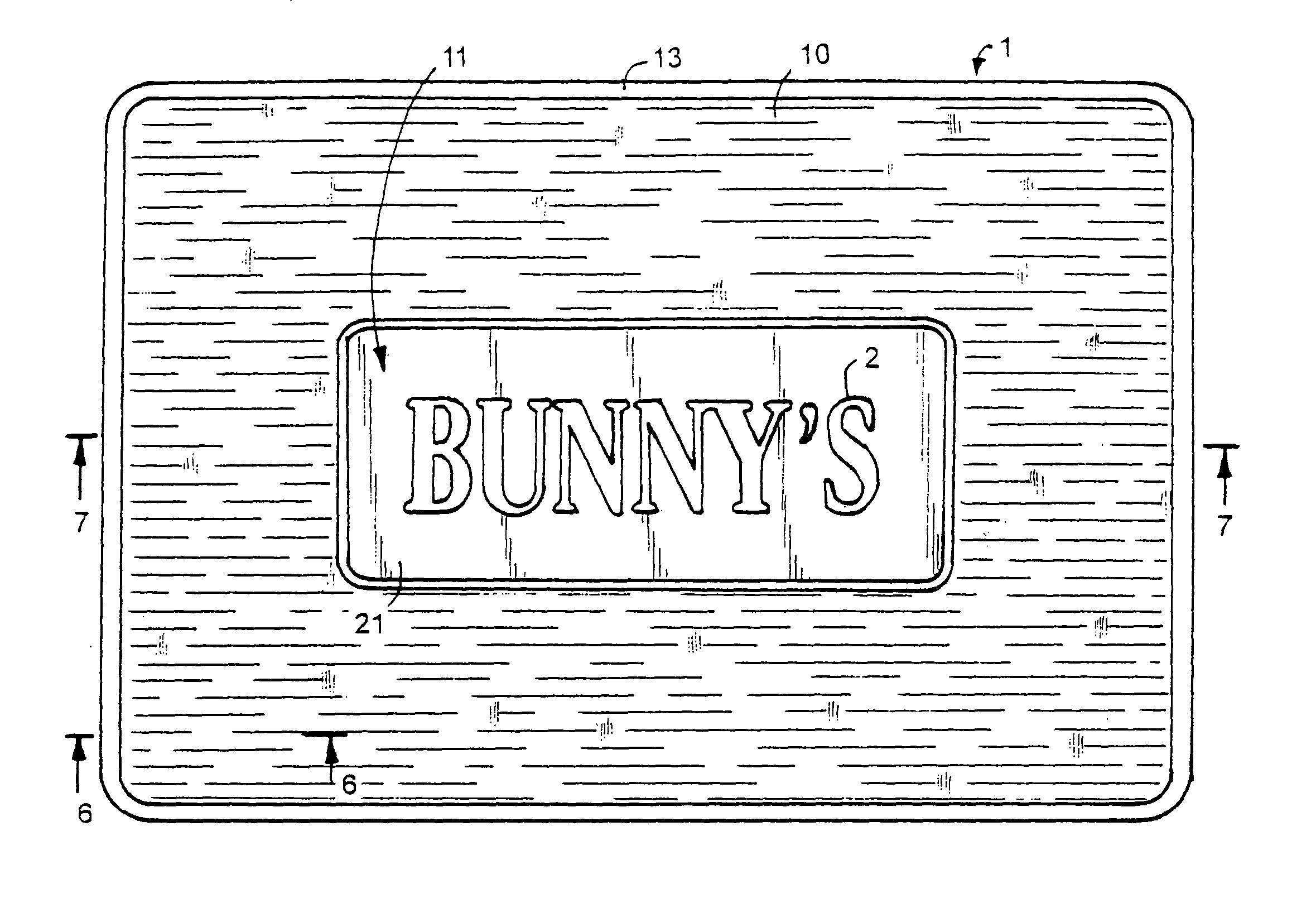
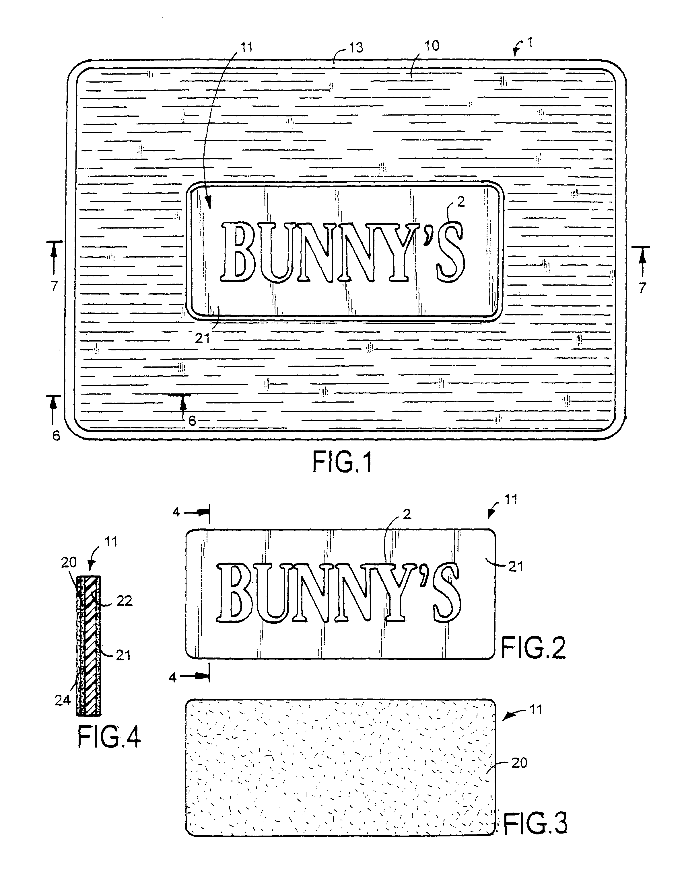
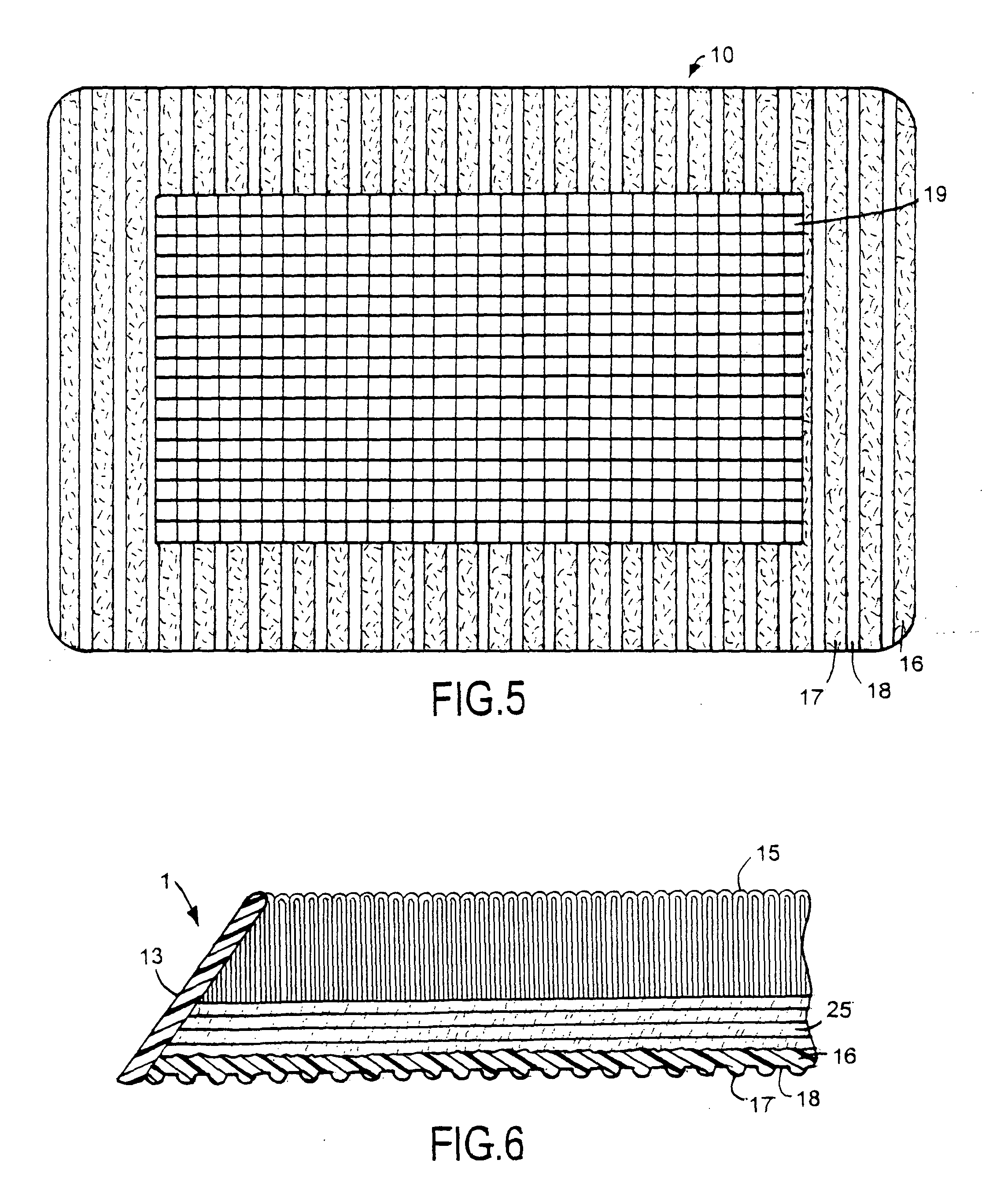
[0030]FIG. 1-8 illustrate an embodiment of the graphic floor mat. Referring to FIG. 1, mat 1 includes a frame member 10 and a replaceable sheet member 11. The face of frame member 10 includes edge 13 which makes up the outer extremities of frame member 10, a surface of fibers 15 and an insert 23 for supporting replaceable sheet member 11. Edge 13 may be oriented at any acute inwardly oriented angle relative to the underlying surface such that it facilitates smooth and uniform transition for any users traversing between the underlying surface and fibers 15. Mat 1 is custom made for commercial or residential buildings as vestibule and entrance mat to divert and displace water, sand, and dirt in all forms so as to prevent the unwanted material from being carried into buildings by persons and wheels. The mat 1 is periodically cleaned to maintain its use as a preventative measure against dirt. Mat 1 holds its shape and position relative to the underlying surface.

[0031]FIG. 2 illustrates ...


PUM

PropertyMeasurementUnit
frictionaaaaaaaaaa
flexibleaaaaaaaaaa
electric conductoraaaaaaaaaa

Abstract

A floor mat has a cavity accommodating an insert supporting a releasable sheet member. An adhesive releasably attaches the sheet member to the insert to allow the sheet member to be removed from the mat and replaced with another sheet member. The sheet member has visual indicia providing persons with information. Signal transmitter and receiver antennas of an electronic article surveillance system are located within the floor mat.

Description

CROSS REFERENCE TO RELATED APPLICATION[0001]This application claims the priority benefit of U.S. Provisional Patent Application Ser. No. 61 / 460,139 filed Dec. 27, 2010.FIELD OF THE INVENTION[0002]The invention relates to floor coverings used as a means to convey information. The floor coverings have safety features which make them suitable for prolonged use.BACKGROUND OF THE INVENTION[0003]Floor coverings have conventionally been used in the prior art to protect and cover an area of a floor which receives relatively high pedestrian traffic. Also, they have been used to reduce fatigue of persons standing on the floor mats by providing cushioning or padding. Some floor coverings include ornamental aspects to improve the aesthetic appearance of the covering. The conventional floor covering has also been adapted to convey information to any person within visual range.[0004]Prior art floor coverings tend to creep and fold due to repeated and prolonged exposure to the elements, pressure, ...

Claims


Application Information

Patent Timeline
Patent Type & Authority Patents(United States)
IPC IPC(8): B32B3/02
CPCY10T428/23907Y10T428/2457Y10T428/24198B32B3/02Y10T428/23929Y10T428/23979B32B9/00B32B2471/04
Inventor CALLAS, MICHAEL, T.
Owner CALLAS ENTERPRISES
Why Eureka
Try Eureka