Actuator

a technology of actuators and actuators, applied in the field of pneumatic actuators, can solve the problems of increasing the friction between the seal and the dynamic seal, impairing the movement of the piston, and sticky and brittle over time, and achieve the effect of easy customization of the actuating mechanism

Active Publication Date: 2014-10-21
MECANIQUE ANALYTIQUE INC
View PDF14 Cites 14 Cited by
  • Summary
  • Abstract
  • Description
  • Claims
  • Application Information

AI Technical Summary

Benefits of technology

[0019]Advantageously, the use of a deformable diaphragm in the actuating mechanism of the present invention eliminates the need for dynamic seals, that is, seals which move with the pistons in conventional actuating mechanisms. Avoiding the use of conventional seals reduces friction of parts within the actuator, increasing in turn the lifetime of the actuating mechanism, regardless of temperature conditions in which it is used. In order to preserve the air-tight properties of the chambers within the mechanism, static seals can be used, such as copper gaskets.
[0022]When pressurized fluid is forced through the cartridge inlet or drawn from the cartridge outlet, or both, the first intermediate chamber expands, moving the intermediate piston from the unactuated position to the actuated position, assisting the sliding of the actuating stem within the cap channel.
[0023]Advantageously, the use of one or several stackable secondary actuating assembly(ies) allows increasing the force applied on the actuating stem.
[0024]In addition, the use of stackable actuating and / or biasing element cartridges allows modifying and controlling the torque and weight force applied on the actuating shaft, allowing easy customization of the actuating mechanism depending on the requirements of the applications for which it is to be used.

Problems solved by technology

When actuators are used in high-temperature applications, sometimes as high as 350° C., the dynamic seals tend to become sticky and brittle over time.
This increases the friction between the seal and the inner wall of the actuating system, impairing movement of the pistons.
Lubricants can be used to minimize this friction, but their use generates other problems: grease-based lubricants, such as Krytox (trademark) or Torr-lube (trademark) eventually dry down, increasing even more the friction and making it harder for the pistons to move.
The use of dry lubricants is usually not considered an alternative, as they are eventually blown away by the actuating gas used.
Similar difficulties are also encountered in solenoid valves in which the pistons are actuated using an electrical current.
The problem is also present in cryogenic applications, where valves are used in very low temperature conditions.
In this case, the humidity present in the actuating gas tends to crystallize at the interface of the pistons and the inner wall of the actuating system, impairing the movement of the pistons.
While the described type of actuator may be appropriate for ambient or relatively medium temperature, it is not readily usable in high temperature or cryogenic applications.
High friction and embrittlement of those O-rings is likely to result if used at cryogenic or at high temperature, like 350° C.
These solutions require the use of several small hard-to-machine parts which render the mechanism complex and difficult to assemble or maintain, in addition to increasing the manufacturing costs.

Method used


Image

  • Actuator
  • Actuator
  • Actuator

Examples


Embodiment Construction

[0061]In the following description, similar features in the drawings have been given similar reference numerals. To preserve the clarity of the drawings, some references numerals have been omitted, if they were already identified in a preceding figure.

[0062]The embodiments described below are given by way of example only and the various characteristics and particularities thereof should not be considered limitative to the scope of the present invention It will be appreciated that positional descriptions such as “top”, “bottom” and the like should, unless otherwise indicated, be taken in the context of the figures and should not be considered limiting.

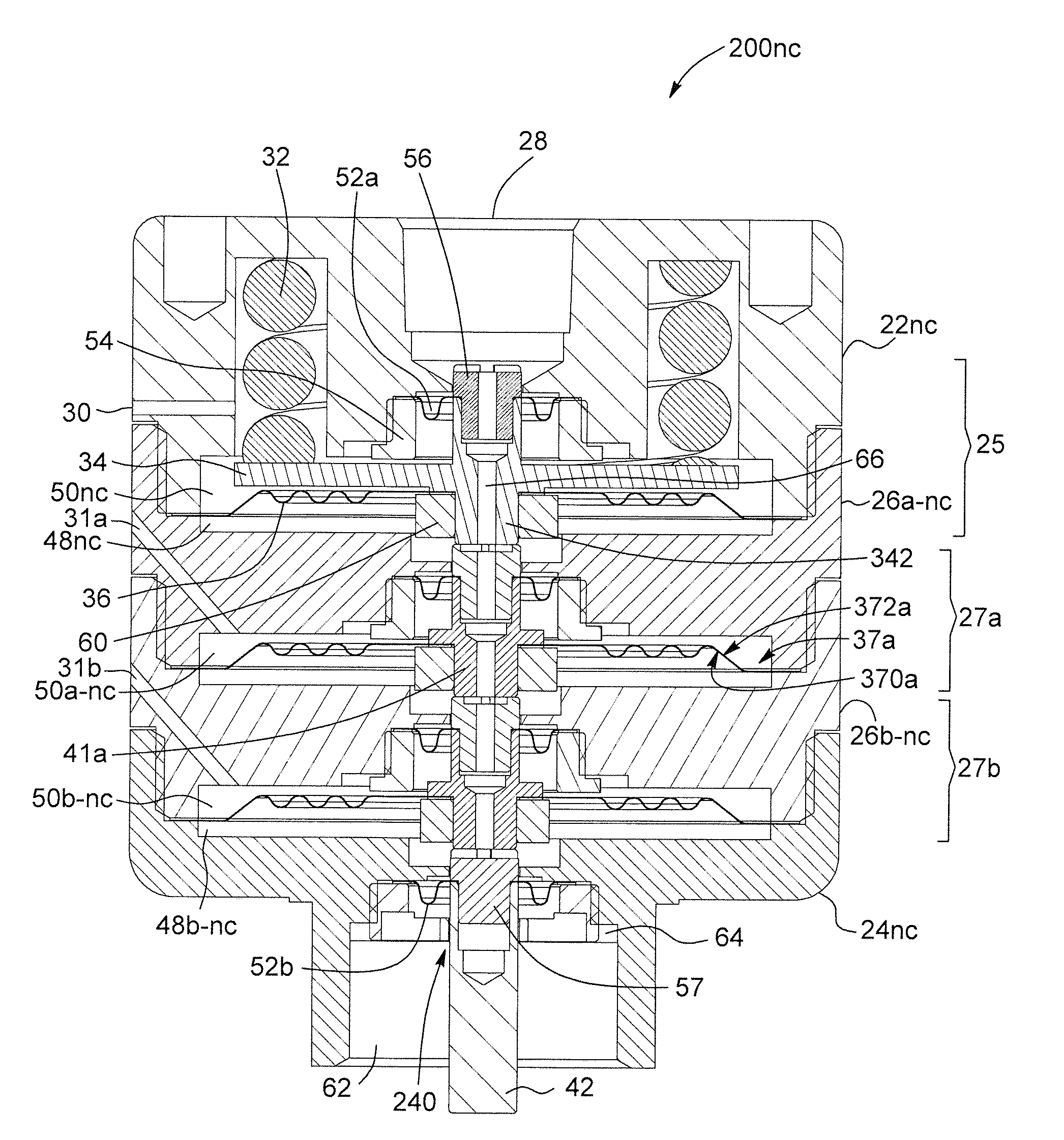
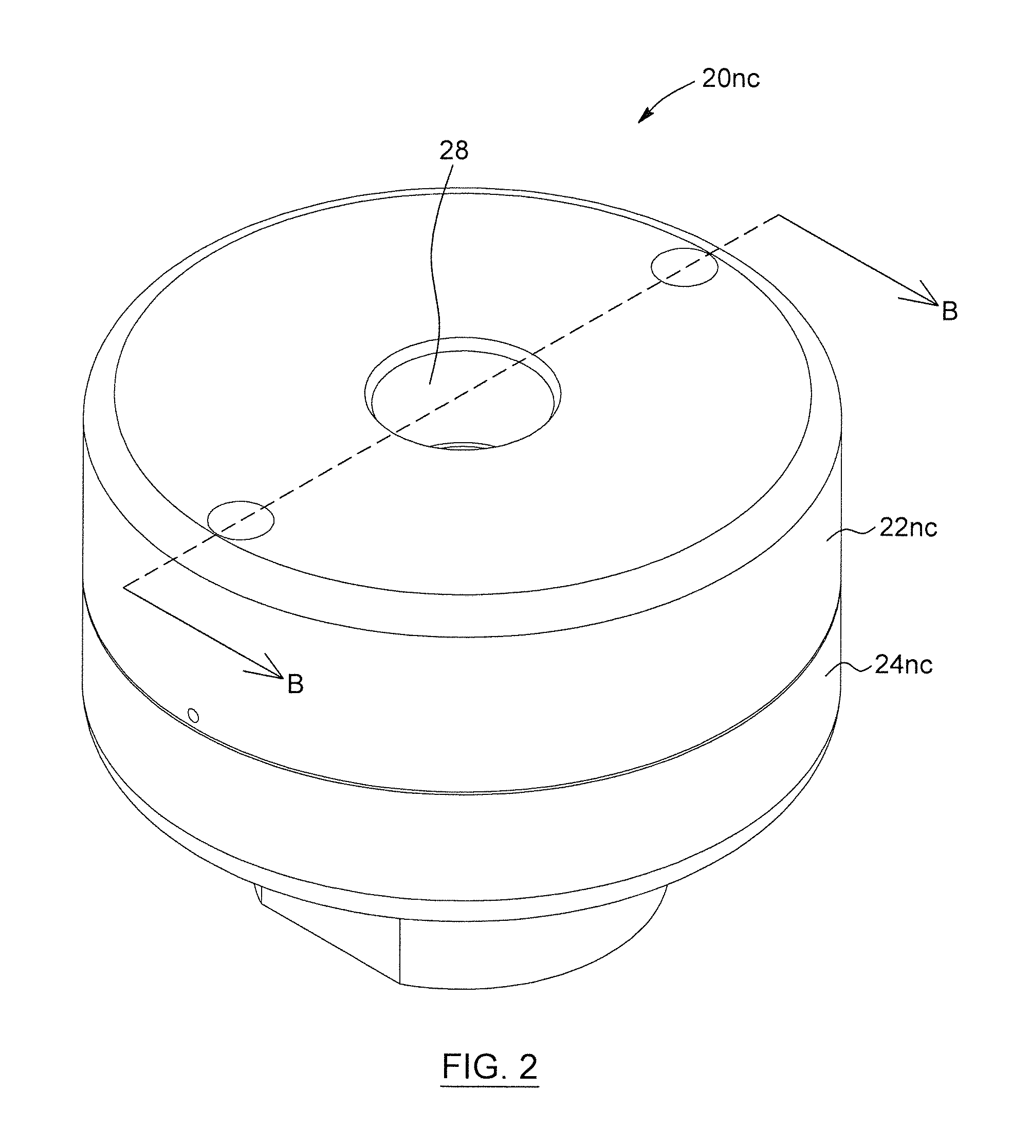
[0063]With reference to FIG. 2, an actuator 20nc for actuating the plunger of valve is shown. The actuator 20nc includes a first cap 22nc and a second cap 24nc, a main inlet 28 and a main outlet 30. The inlet 28 and outlet 30 are ports through which fluid can be forced or drawn. The main inlet 28 is provided in the top cap 22nc. The fir...


PUM


Abstract

An actuator for actuating a plunger of a valve is provided. The actuator has an inlet and includes first and second hollow caps. A main actuation assembly is provided between the caps. The main actuation assembly includes a deformable diaphragm; first and second chambers, static sealing elements and a main piston movable between actuated and unactuated positions. A biasing mechanism biases the piston in the unactuated position. When pressurized gas is flown through the inlet and / or drawn from the outlet of the actuator, the first chamber expands, moving the main piston from the unactuated position to the actuated position, an actuating stem connected to the main piston thereby sliding within a channel provided in the bottom cap. Stackable actuating assemblies can also be used between the caps. Using static sealing elements advantageously avoids friction between moving parts.

Description

FIELD OF THE INVENTION[0001]The present invention generally relates to actuators and more particularly concerns a pneumatic actuator used to actuate plungers or pistons in valves.BACKGROUND[0002]Pneumatic actuators are used in different types of applications, and serve to actuate or move plungers, shafts and the likes in different types of devices, such as valves.[0003]An actuator can include a normally closed piston, a normally open piston, or both within the same assembly. An actuator including a normally closed piston is typically provided with a biasing element, such as a spring or Belleville washers, which biases the piston in a closed position. In order to move the piston from the closed to the open position, gas is injected within the actuator, counteracting the biasing action of the spring and allowing the piston to move towards the open position. Similarly, normally opened pistons may be biased in their open position and moved to the closed position through the effect of ga...

Claims


Application Information

Patent Timeline
Patent Type & Authority Patents(United States)
IPC IPC(8): F16K31/00F15B11/12F16J3/02F15B11/036F15B15/10F16K31/126
CPCF16K31/126F16K31/1262F16K31/1268F15B15/10F16K31/165F15B11/036Y10T137/0491
Inventor GAMACHE, YVES
Owner MECANIQUE ANALYTIQUE INC
Why Eureka
Try Eureka