Fiber optic enclosures employing clamping assemblies for strain relief of cables, and related assemblies and methods

a technology of fiber optic enclosures and clamping assemblies, applied in the direction of optical elements, instruments, manufacturing tools, etc., can solve the problems that conventional mechanisms providing strain relief occupy valuable space in the fiber optic enclosure, and achieve the effect of reducing signal attenuation

Inactive Publication Date: 2014-10-28
CORNING OPTICAL COMM LLC
View PDF593 Cites 28 Cited by
  • Summary
  • Abstract
  • Description
  • Claims
  • Application Information

AI Technical Summary

Benefits of technology

[0010]In one embodiment, an elongated member is disclosed for sealing off an opening located through an enclosure wall of a fiber optic enclosure. The fiber optic enclosure may have a plurality of fiber optic cables disposed therethrough. The elongated member may include a first end and a second end disposed opposite the first end along a longitudinal axis. The second end may be configured to guide a plurality of fiber optic cables into the opening of the enclosure. The elongated member may also include a strain relief portion disposed at the first end. The strain relief portion may include a plurality of recesses forming a plurality of openings. The plurality of recesses may be configured to each receive one of the plurality of fiber optic cables. Each of the plurality of recesses may be separated by one of a plurality of external surfaces and disposed parallel to the longitudinal axis. The elongated member may also include a clamping assembly. The clamping assembly may be configured to clamp strength members of the plurality of fiber optic cables. This embodiment may provide strain relief to the fiber optic cables through the strength members and thereby may reduce damage to the fiber optic cables.
[0012]As part of this embodiment, the locknut may be configured to be removeably attached to the first cable fitting end and may be configured to pull the base wall surface against the contact area. The elongated member may include a first end and a second end. The first end may be disposed within the orifice of the elongated cable fitting body. The first end may also be opposite a second end along a longitudinal axis. The elongated member may also include a strain relief portion disposed at the first end. The strain relief portion may include a plurality of recesses forming a plurality of openings that are configured to each receive one of the plurality of fiber optic cables. Each of the plurality of recesses may be separated by one of a plurality of external surfaces and disposed parallel to the longitudinal axis. The elongated member may also include a clamping assembly disposed at the first end. The clamping assembly may be configured to clamp strength members of the plurality of fiber optic cables. This embodiment may provide strain relief to the plurality of fiber optic cables exiting through the opening of the fiber optic enclosure and thereby may reduce signal attenuation for signals traveling over the plurality of fiber optic cables.
[0013]In another embodiment, a method is disclosed for installing a cable fitting assembly with a plurality of fiber optic cables into an opening of a fiber optic enclosure. This method may include inserting a first cable fitting end of an elongated cable fitting body through an opening of a fiber optic enclosure and securing the first cable fitting end to the fiber optic enclosure with a locknut. Next, the method may also include inserting an end of the plurality of fiber optic cables through an orifice of the elongated cable fitting body. The method may also include receiving a threaded bushing through a bushing opening and into a bushing bore disposed at a first end of an elongated member. Next, the method may include stripping the plurality of fiber optic cables from the end of the fiber optic cables to a transition point and separating strength members of the plurality of fiber optic cables from optical fibers of the plurality of fiber optic cables. Next, the method may also include creating a strength member gap. The method may also include receiving the plurality of fiber optic cables through a plurality of openings into a plurality of recesses in a strain relief portion disposed at the first end of the elongated member. Each of the plurality of recesses may be separated by one of a plurality of external surfaces and disposed parallel to the longitudinal axis. The method may also include engaging a clamping assembly. This embodiment may provide an efficient manner to provide strain relief for the plurality of fiber optic cables installed into the opening of the fiber optic enclosure.

Problems solved by technology

The fiber optic cables exiting a fiber optic terminal may need strain relief as optical fiber movement may damage the cable or cause signal attenuation.
Conventional mechanisms providing strain relief occupy valuable space in the fiber optic enclosure that could be used for additional fiber optic equipment.

Method used


Image

  • Fiber optic enclosures employing clamping assemblies for strain relief of cables, and related assemblies and methods
  • Fiber optic enclosures employing clamping assemblies for strain relief of cables, and related assemblies and methods
  • Fiber optic enclosures employing clamping assemblies for strain relief of cables, and related assemblies and methods

Examples


Embodiment Construction

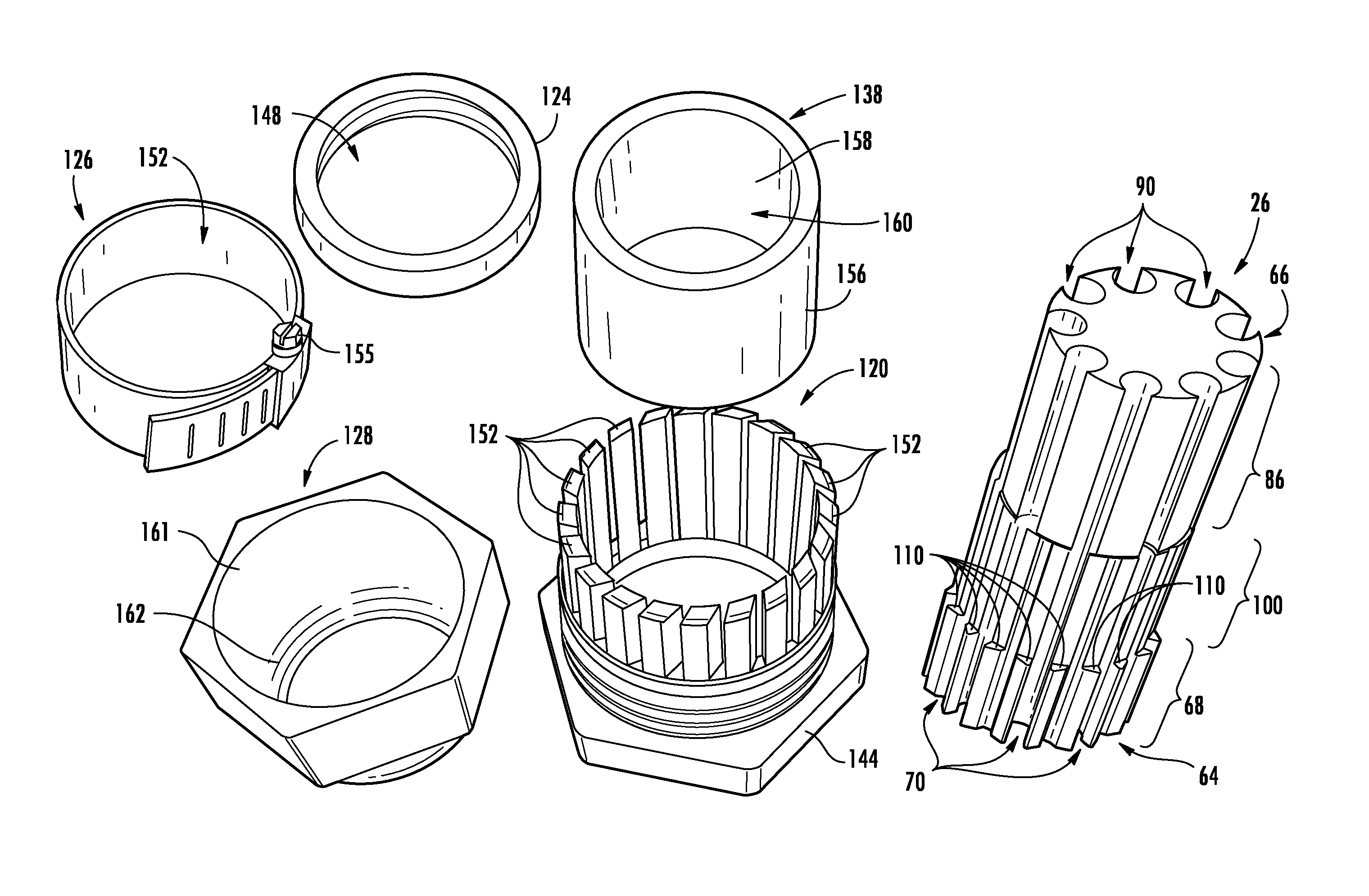
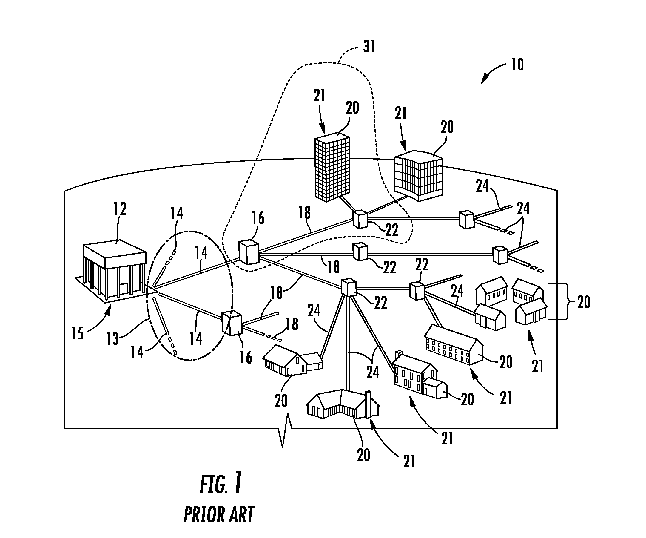
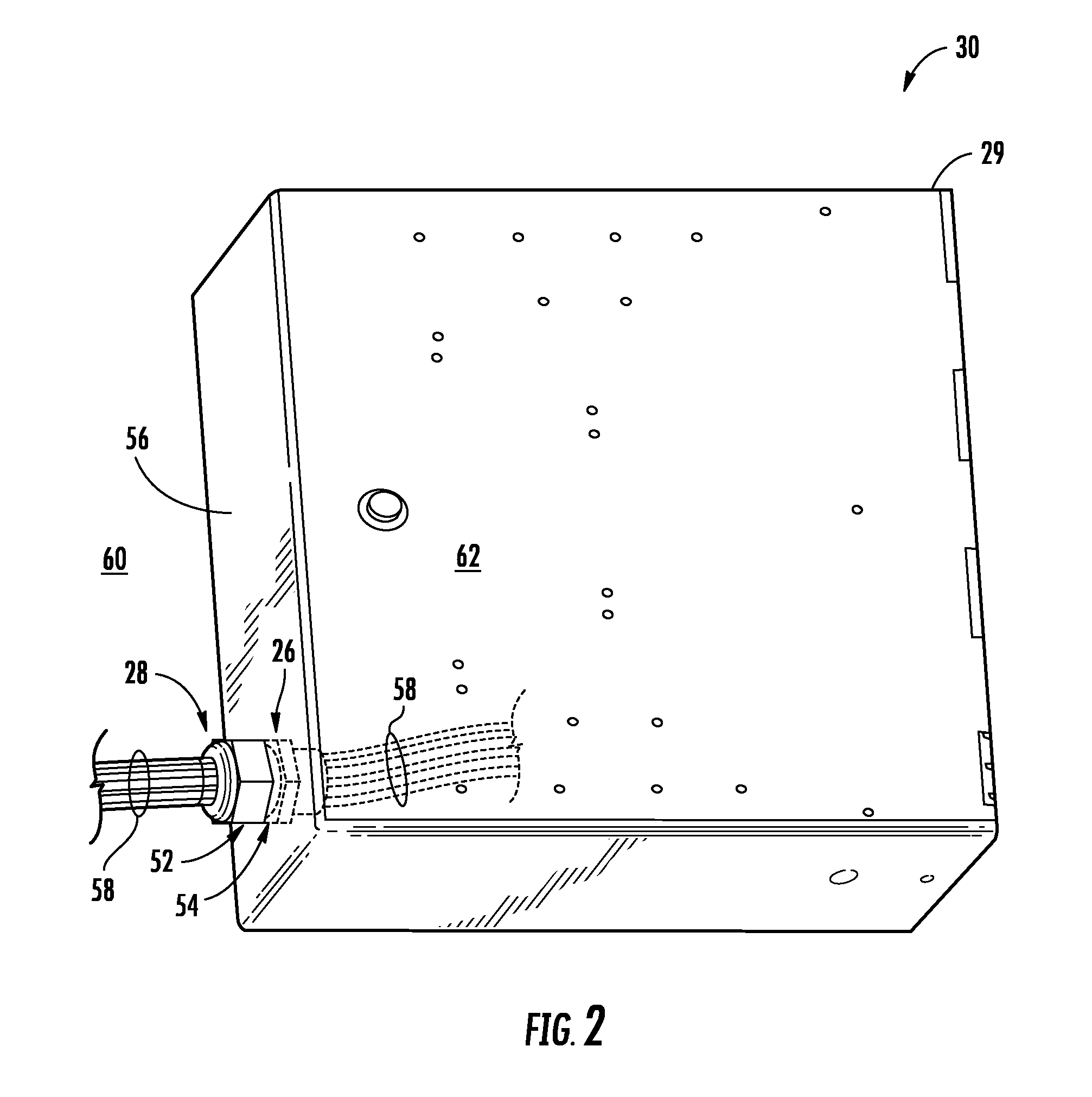
[0009]Embodiments disclosed herein include fiber optic enclosures employing clamping assemblies for strain relief of cables, and related assemblies and methods. The fiber optic enclosures may be part of a fiber optic terminal in a fiber optic network. The fiber optic enclosures may include openings in the walls of the fiber optic enclosure. A cable fitting assembly may be attached to a portion of the wall around an opening to form a passageway for fiber optic cables to enter the fiber optic enclosure. An elongated member may be used to guide the fiber optic cables through the passageway. The elongated member may have a first end and second end. The elongated member may include a clamping assembly at the first end to provide strain relief to the fiber optic cables by clamping strength members of the fiber optic cables.

[0010]In one embodiment, an elongated member is disclosed for sealing off an opening located through an enclosure wall of a fiber optic enclosure. The fiber optic enclo...


PUM

PropertyMeasurementUnit
diametersaaaaaaaaaa
diametersaaaaaaaaaa
diameteraaaaaaaaaa

Abstract

Fiber optic enclosures employing clamping assemblies for strain relief cables and related assemblies and methods are disclosed. The fiber optic enclosures may be part of a fiber optic terminal in a fiber optic network. The fiber optic enclosures may include openings in the walls of the fiber optic enclosure. A cable fitting assembly may be attached to a portion of the wall around an opening to form a passageway for fiber optic cables to enter the fiber optic enclosure. An elongated member may be used to guide the fiber optic cables through the passageway. The elongated member may have a first end and second end. The elongated member may include a clamping assembly at the first end to provide strain relief to the fiber optic cables by clamping strength members of the fiber optic cables.

Description

BACKGROUND[0001]1. Field of the Disclosure[0002]The technology of the disclosure relates to fiber optic equipment, such as local convergence points (LCPs) and fiber distribution terminals (FDTs), and strain relief of fiber optic cables disposed therein which provide fiber optic connections to subscribers.[0003]2. Technical Background[0004]To provide improved performance to subscribers, communication and data networks are increasingly employing optical fiber. The benefits of optical fiber are well known and include higher signal-to-noise ratios and increased bandwidth. To further improve performance, fiber optic networks are increasingly providing optical fiber connectivity all the way to end subscribers. These initiatives include various fiber-to-the-premises (FTTP), fiber-to-the-home (FTTH), and other fiber initiatives (generally described as FTTx). In this regard, FIG. 1 illustrates an exemplary fiber optic network 10. The fiber optic network 10 in this example is a passive optica...

Claims


Application Information

Patent Timeline
Patent Type & Authority Patents(United States)
IPC IPC(8): G02B6/00
CPCG02B6/4248G02B6/4428G02B6/4471Y10T29/49826
Inventor BEAMON, HUBERT BLAIRCOX, TERRY DEAN
Owner CORNING OPTICAL COMM LLC
Why Eureka
Try Eureka