Eureka AIR delivers breakthrough ideas for toughest innovation challenges, trusted by R&D personnel around the world.

Dynamic tracking of moving targets

Active Publication Date: 2014-10-28
ACCURAY
View PDF64 Cites 21 Cited by
  • Summary
  • Abstract
  • Description
  • Claims
  • Application Information

AI Technical Summary

Benefits of technology

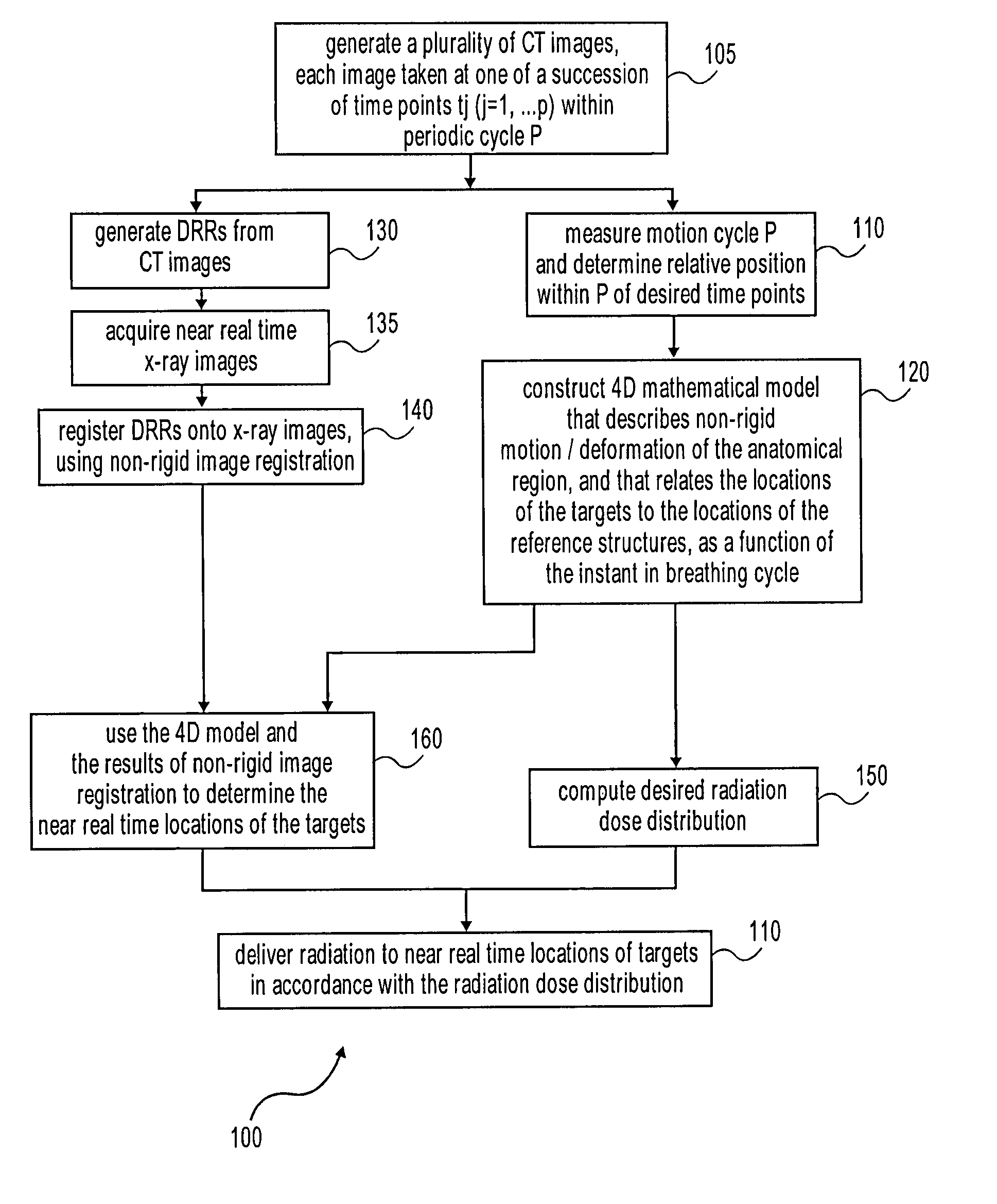
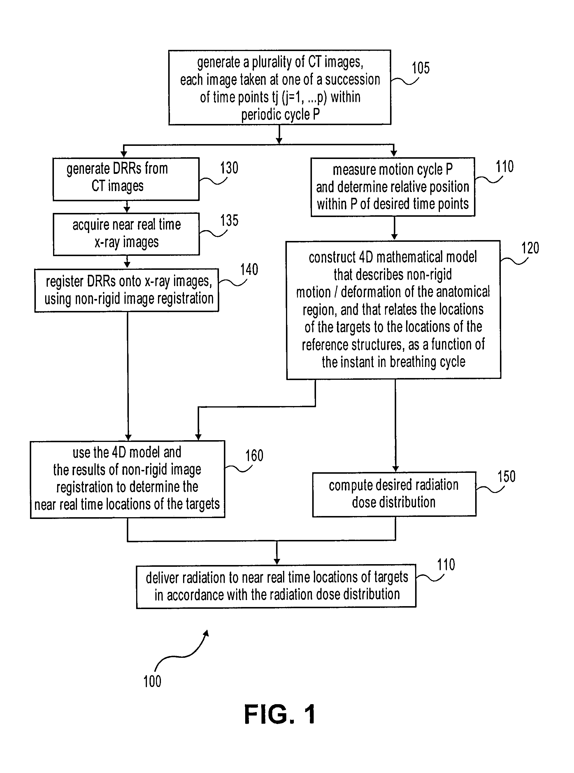
The patent describes a method and system for dynamically tracking targets in an anatomical region to deliver therapeutic radiation while the region is undergoing motion. The targets can be tumors or lesions, and the motion can be periodic or aperiodic. The method involves constructing a 4D mathematical model that describes the non-rigid deformation and motion of the anatomical region, and using this model to generate a radiation dose distribution that prescribes the desired amount of radiation to be delivered in real-time to the targets. The system includes motion sensors to determine the relative position of the targets within the motion cycle. The treatment planning generator synchronizes the radiation beam delivery to the breathing cycle determined in the treatment planning. The technical effect of this patent is to enable more accurate and effective radiation therapy while the anatomical region is in motion.

Problems solved by technology

Fiducials-based tracking can be difficult for a patient, for a number of reasons.
For example, high accuracy tends to be achieved by using bone-implanted fiducial markers, but less invasive techniques such as skin-attached markers or anatomical positions tend to be less accurate.
Implantation of fiducials into a patient is generally painful and difficult, especially for the C-spine, the implantation process for which may frequently lead to clinical complications.
These methods do not take into account the non-rigid motions and deformations of the surrounding anatomy, as a function of the motion cycle.

Method used


Image

  • Dynamic tracking of moving targets
  • Dynamic tracking of moving targets
  • Dynamic tracking of moving targets

Examples


Embodiment Construction

[0032]A number of techniques are described for dynamically tracking tumors / lesions in the human body that is undergoing motion. The methods are of principal use in radiosurgery, but may also be useful in other applications where it may be necessary to dynamically track parts of the anatomy that move, for example because of respiration or heartbeat.

[0033]Some portions of the detailed description that follows are presented in terms of algorithms and symbolic representations of operations on data bits within a computer memory. These algorithmic descriptions and representations are the means used by those skilled in the data processing arts to most effectively convey the substance of their work to others skilled in the art. An algorithm is conceived to be a self-consistent sequence of acts leading to a desired result. These acts require physical manipulations of physical quantities. Usually, though not necessarily, these quantities may take the form of electrical or magnetic signals cap...


PUM


Abstract

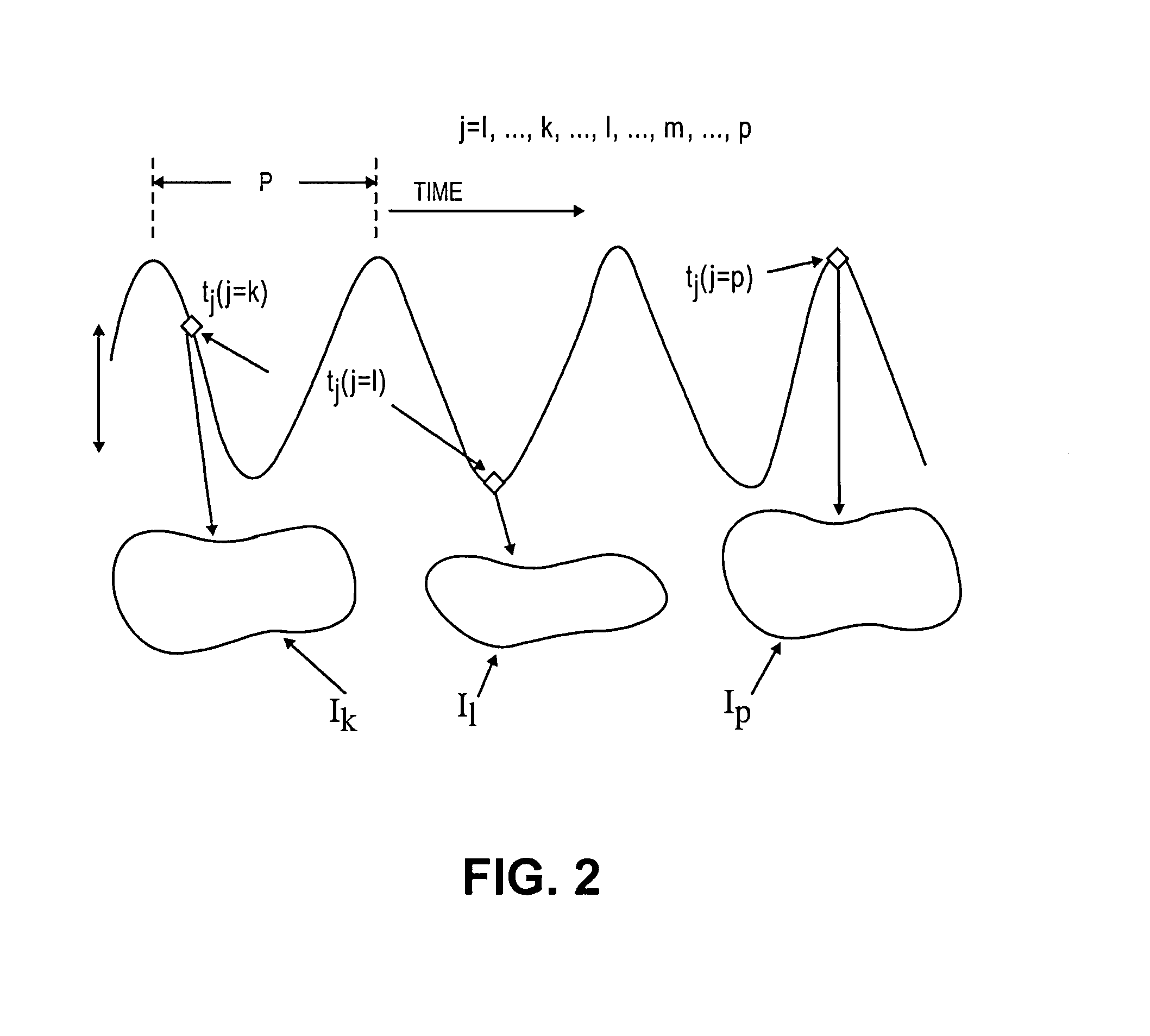
Treatment targets such as tumors or lesions, located within an anatomical region that undergoes motion (which may be periodic with cycle P), are dynamically tracked. A 4D mathematical model is established for the non-rigid motion and deformation of the anatomical region, from a set of CT or other 3D images. The 4D mathematical model relates the 3D locations of part(s) of the anatomical region with the targets being tracked, as a function of the position in time within P. Using fiducial-less non-rigid image registration between pre-operative DRRs and intra-operative x-ray images, the absolute position of the target and / or other part(s) of the anatomical region is determined. The cycle P is determined using motion sensors such as surface markers. The radiation beams are delivered using: 1) the results of non-rigid image registration; 2) the 4D model; and 3) the position in time within P.

Description

REFERENCE TO RELATED APPLICATION[0001]This application is a divisional of application Ser. No. 10 / 957,467, filed Sep. 30, 2004, which is hereby incorporated by reference.BACKGROUND[0002]In some medical applications, it may be necessary to dynamically track targets that move with time. For example, in radiosurgery it may be desirable to dynamically track tumors and / or lesions in the human body that move with respiration and / or heartbeat. In radiosurgery, accurate trajectories of the radiation beams through the patient anatomy to the lesion or tumor being treated can be critical, in order to achieve the radiation dose distribution that was computed during treatment planning time. For regions of the human anatomy that move, for example due to breathing or heartbeat, it is important to take such motions into consideration, when computing the effect of the motion on the treatment plan being generated. Dynamic tracking may also be useful in applications other than radiosurgery in which pa...

Claims


Application Information

Patent Timeline
IPC IPC(8): A61B6/00A61B19/00A61B17/00A61B5/05A61N5/10A61B6/03A61B5/113
CPCA61B2019/5265A61B2019/524A61B5/113A61N5/1067A61B6/032A61N2005/1062A61B6/5217A61B19/5244A61N5/1037A61B2017/00694A61N2005/1052A61B2019/207A61N5/1064A61B2019/5295A61N5/1049A61B2019/505A61B6/037A61N2005/1061A61B19/52A61N2005/1055A61B5/055A61B6/12A61N5/1039A61B90/36A61B2090/367A61B34/20A61B2090/101A61B2034/105A61B2090/3762A61B2034/2065G16H50/30
Inventor THOMSON, EUANDOOLEY, JOHN ROBINSONKUDUVALLI, GOPINATHWANG, JAMESEARNST, ERICRAANES, CHRIS
Owner ACCURAY
Why Eureka
Eureka Blog
Learn More