Device for lubricating an epicycloidal reduction gear

a technology of cycloidal reduction gear and lubricating device, which is applied in the direction of gearing details, machines/engines, mechanical apparatus, etc., can solve the problems of high oil flow rate, system disadvantages, consequential footprint, etc., and achieve the effect of incompatible lifetime wear and consequential footprin

Active Publication Date: 2014-11-04
SN DETUDE & DE CONSTR DE MOTEURS DAVIATION S N E C M A
View PDF14 Cites 15 Cited by
  • Summary
  • Abstract
  • Description
  • Claims
  • Application Information

AI Technical Summary

Benefits of technology

The patent describes a reduction gear that can be flexibly installed in a turbojet. This device allows for the transfer of lubrication oil from the fixed components to the moving components without the need for a rotating seal. The technical effect of this invention is improved efficiency and flexibility in the installation of a reduction gear in a turbojet.

Problems solved by technology

One of the problems encountered with the reduction gears on turbofans is that they require high oil flow rates, which can be as high as 6 to 7000 l / h on take-off, to ensure their lubrication and the cooling of their pinions and main bearings.
On the other hand, they have the drawback of having planet pinions which move by rotating about the axis of rotation of the reduction gear drive shaft.
These systems nevertheless have the drawbacks of a consequential footprint and a wear which is incompatible with the lifetimes demanded of aeronautical engines.
They also exhibit risks of failures which would give rise to an interruption of the oil feed, which is not acceptable given the potentially catastrophic consequences of an engine stopping in flight as a result of a jamming of its reduction gear.
Finally, it is difficult to make these reduction gears compatible with a flexible installation on the structure of the engine, which is recommended to mitigate the risk of loss or rupture of a fan blade, or even with an installation of modular type to facilitate the assembly of an engine.

Method used


Image

  • Device for lubricating an epicycloidal reduction gear
  • Device for lubricating an epicycloidal reduction gear
  • Device for lubricating an epicycloidal reduction gear

Examples


Embodiment Construction

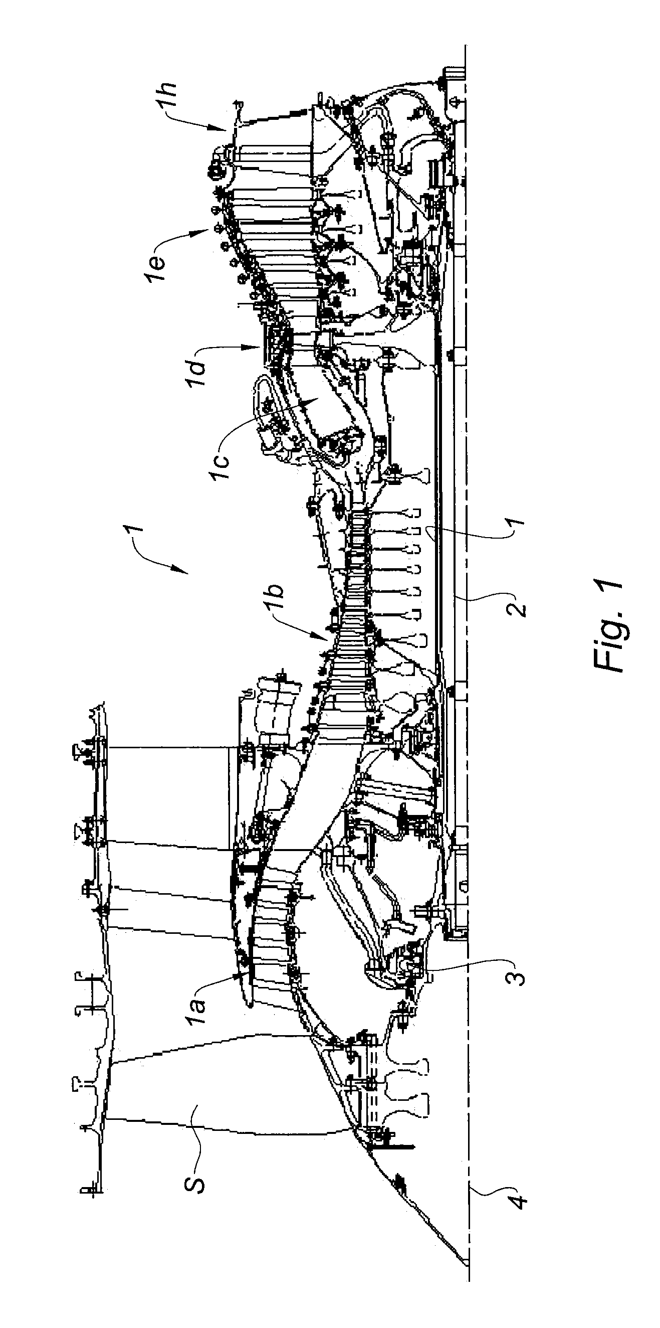
[0024]By referring to FIG. 1, a turbojet 1 can be seen which comprises, conventionally, a fan S, a low-pressure compressor 1a, a high-pressure compressor 1b, a combustion chamber 1c, a high-pressure turbine 1d, a low-pressure turbine 1e and an exhaust nozzle 1h. The high-pressure compressor 1b and the high-pressure turbine 1d are linked by a high-pressure shaft 1 and form with it a high-pressure (HP) core. The low-pressure compressor 1a and the low-pressure turbine 1e are linked by a low-pressure shaft 2 and form with it a low-pressure (BP) core.

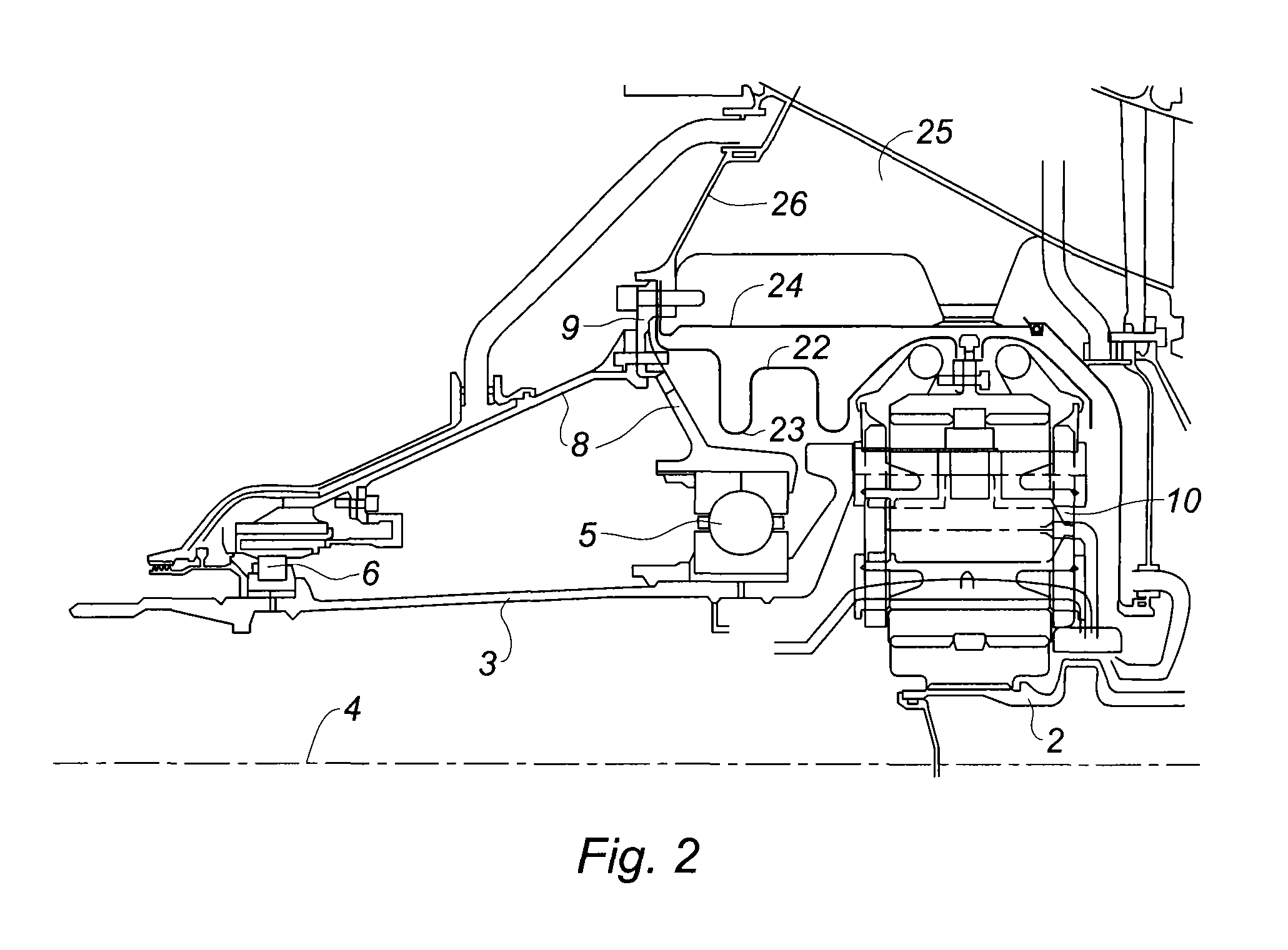
[0025]In the configuration represented which relates to a conventional turbofan, without reduction gear, the disc on which the blades of the fan S are mounted is driven by a fan shaft 3, or BP journal, which is itself driven directly by the BP shaft 2. In the invention represented in FIGS. 2 to 6, the fan shaft 3 is driven by the BP shaft 2 through a reduction gear 10 with epicycloidal gear train.

[0026]FIG. 2 shows the positioning of the red...


PUM


Abstract

A reduction gear includes a sun pinion and planet pinions driven by the sun pinion and rolling on a fixed ring gear. The device includes an oil tank, an oil supply duct and oil routing ducts. The device also includes an oil ejection device at the end of the fixed supply duct, the orientation of which includes a radial component directed away from a common axis of rotation, and a cylindrical device for recovering the oil that can move in rotation about the common axis of rotation. The oil ejection device is linked by at least one duct to a lubrication device for the gear formed by the cooperation of the teeth of at least one planet pinion with an adjacent pinion. This device feeds the ducts which supply the oil to the parts to be lubricated, by virtue of the action of the centrifugal field.

Description

BACKGROUND OF THE INVENTION[0001]1. Field of the Invention[0002]The field of the invention is that of aeronautical propulsion and more particularly turbojet engines with high dilution rates, or turbofans.[0003]2. Description of the Related Art[0004]Modern turbomachines are conventionally produced in the form of an assembly of modules which can include fixed parts and moving parts. A module is defined as a subassembly of a turbomachine which exhibits geometrical characteristics at its interfaces with the adjacent modules that are sufficiently precise for it to be able to be shipped individually and which has undergone a particular balancing when it includes rotating parts. The modules are assembled to form a complete engine, minimizing the operations of balancing and of the matching interfaced parts.[0005]The current turbofans comprise a number of compressor stages, notably a low-pressure (BP) and a high-pressure (HP) compressor which belong to the primary core of the engine. Upstrea...

Claims


Application Information

Patent Timeline
IPC IPC(8): F01D25/18F16H57/04
CPCY02T50/671F01D25/18F16H57/0423F05D2260/98F16H57/0479F16H57/0486F16H57/0456F16H57/042F05D2260/40311Y02T50/60F16H57/0421F16H57/0482F16H57/08
Inventor GALLET, FRANCOISBRIANTAIS, BORISSEREY, JEAN-PIERRETAN-KIM, ALEXANDRE
Owner SN DETUDE & DE CONSTR DE MOTEURS DAVIATION S N E C M A
Why Eureka
Try Eureka