Disposable cylindrical cutter

a cylindrical cutter and disassembly technology, applied in the field of disassembly cutters, can solve the problems of difficult to properly fit an implant over the end, unsatisfactory patient outcomes, and 10/b> not removing all the bone, so as to avoid the need for expensive machining and grinding operations, and reduce the cost of production. , the effect of low cos

Active Publication Date: 2014-11-04
WILSON GREATBATCH LTD
View PDF42 Cites 4 Cited by
  • Summary
  • Abstract
  • Description
  • Claims
  • Application Information

AI Technical Summary

Benefits of technology

[0012]Furthermore, it is preferred that the distal base portion of the centrally located second cylinder is recessed or offset from the distal base of the first cylinder. This recess establishes an offset rim formed by the wall thickness of the first cylinder. The depth of the offset rim is determined by the gap between the distal base plane of the first cylilnder and the distal base plane of the second cylinder. The offset rim provides a barrier that prevents unintentional damage to nearby bone and / or tissue resulting from contact with the cutting surface of the insert blades or cutting disc.
[0014]Another feature of the boss is that it acts as a “stop” to prevent overcutting of the bone. As will be explained in greater detail, the distal end of the boss comes into contact with the end of the bone thus preventing further advancement of the cutter. As such, the position of the boss preferably determines the depth of cut into the bone and prevents unintentional overcutting of the end of the bone.
[0018]In this embodiment, the cylindrical cutter is assembled by pressing the insert blades into the blade enclosures of the assembly. The insert blades are designed such that they snap into the blade enclosure. This low cost production process, along with the economical production of the component parts, avoids the need for expensive machining and grinding operations that are common with the prior art.

Problems solved by technology

Using a dull cutter generates heat that typically leads to tissue necrosis and results in undesireable patient outcomes.
A non-sterile cutter blade typically results in an infected and damaged bone that may lead to other problems for the patient.
However, these prior devices 10 do not remove all the bone 14 required to properly fit an implant.
Such a bone removal procedure makes it difficult to properly fit an implant over the end 24 of the bone 14.
If the implant is not properly fit over the end 24 of the bone 14, undesirable implant wear or improper implant operation could result.
In addition to the inefficient bone removal limitations, traditional bone cutters are typically reused multiple times. That is because of their high cost.
Furthermore, over time, as these cutters are used and reused, they become dull, thus requiring resharpening.
However, these resharpening and sterilization processes add additional costs and increase the possibility of infection.
In addition, resharpening tends to deform the dimensions of the cutter.
Furthermore, there is a high likelihood that the cleaning and sterilization process may not remove all possible infection agents such as bacteria, machining lubricants, and the like.

Method used


Image

  • Disposable cylindrical cutter
  • Disposable cylindrical cutter
  • Disposable cylindrical cutter

Examples


Embodiment Construction

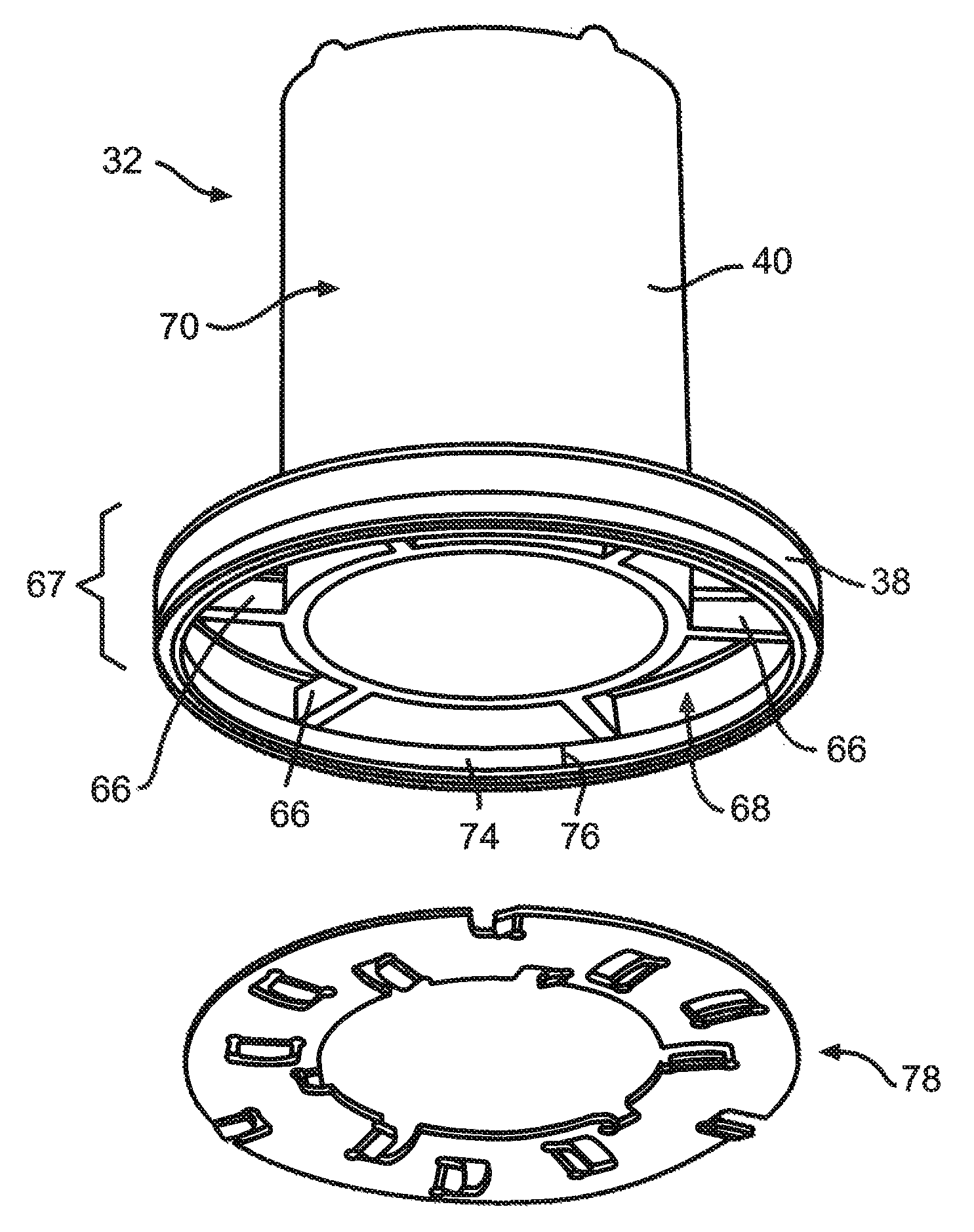
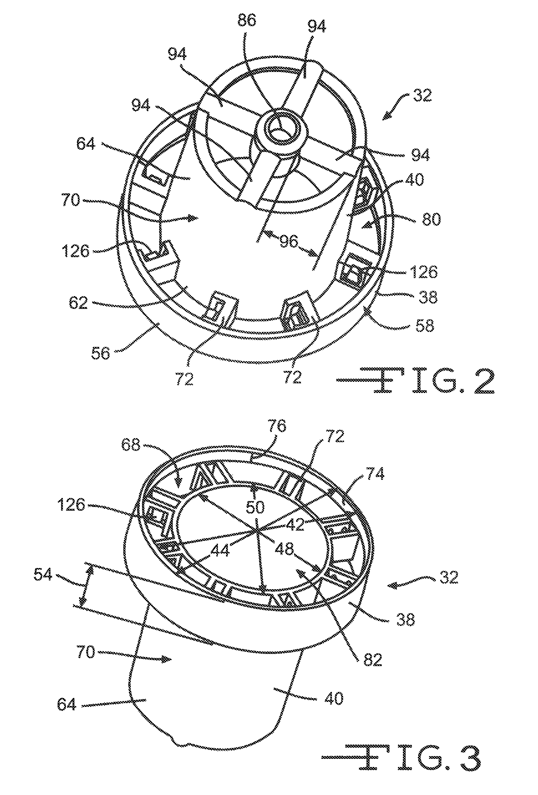
[0037]Now turning to the figures, FIGS. 2-11A illustrate embodiments of a bone cutter 30 of the present invention. In a preferred embodiment, the bone cutter 30 comprises a cutter housing 32, cutter blades 34 or cutter disc 78, and a guide rod 36 (FIGS. 11, 11A).

[0038]As shown in FIGS. 2-4, 8, 8A, and 10-11A, the cutter housing 32 preferably comprises two cylinders, a first cylinder 38 and a second cylinder 40 that are joined therebetween. In a preferred embodiment, the first cylinder 38 comprises a first cylinder inner diameter 42, a first cylinder outer diameter 44, and a first cylinder wall thickness 46 therebetween. The second cylinder 40 comprises a second cylinder inner diameter 48, a second cylinder outer diameter 50, and a second cylinder wall thickness 52 therebetween.

[0039]In addition, the first cylinder 38 comprises a first cylinder height 54 extending from a first cylinder distal base portion 56 to a first cylinder proximal end portion 58. In a preferred embodiment, the ...


PUM


Abstract

A single use bone cutter comprised of two concentric cylinders and a series of insert blades or cutter disc is described. The cutter blades or cutter disc is preferably positioned at the distal end of the cutter. The bone cutter also comprises a guide rod that aids in the line of sight when using the cutter device.

Description

CROSS-REFERENCE TO RELATED APPLICATIONS[0001]This application claims priority from U.S. Provisional Patent Application Ser. No. 61 / 346,976, filed May 21, 2010.FIELD OF THE INVENTION[0002]The present invention relates to the art of orthopedic cutting tools, and more particularly, to a disposable cutter used for shaping and preparing the femoral bone for implant insertion.PRIOR ART[0003]Cutting tools used in orthopedic procedures are designed to cut bone and associated tissue matter. Specifically, cutters of the present invention are designed to cut and shape the end of a long bone such as a femur or humerus. Typically, the end of the long bone is cut and shaped for insertion of an implant. As such, these cutters are required to be sterile and sharp. Using a dull cutter generates heat that typically leads to tissue necrosis and results in undesireable patient outcomes. A non-sterile cutter blade typically results in an infected and damaged bone that may lead to other problems for the ...

Claims


Application Information

Patent Timeline
Patent Type & Authority Patents(United States)
IPC IPC(8): A61B17/17A61B17/16
CPCA61B17/175A61B17/1668A61B17/1735A61B17/162A61B17/1637A61B17/1642A61B17/1659
Inventor VICTOR, GARY, C.
Owner WILSON GREATBATCH LTD
Why Eureka
Try Eureka