Flexible circuit cable with at least two bundled wire groups

a flexible circuit cable and wire group technology, applied in the direction of insulated conductors, flat/ribbon cables, cables, etc., can solve the problems of signal transmission efficiency and other problems, and achieve the effect of effectively suppressing electromagnetic interference, reducing the problem of mutual interference, and reducing the effect of signal transmission efficiency

Active Publication Date: 2014-11-04
ADVANCED FLEXIBLE CIRCUITS
View PDF14 Cites 1 Cited by
  • Summary
  • Abstract
  • Description
  • Claims
  • Application Information

AI Technical Summary

Benefits of technology

[0007]Thus, an object of the present invention is to provide a flexible circuit cable that comprises at least two bundled wire groups in order to overcome the drawbacks of the conventional cables in practical applications.
[0009]The technical solution of the present invention separates a power wire group, a grounding wire group, and a signal wire group so as to effectively suppress electromagnetic interference induced by the power wire group affecting the signal transmission efficiency of the signal wire group. Further, the bundling members can be selectively made of one of insulation material, conductive fabric, and electromagnetic shielding material according to the signal groups. For example, the bundling member of the power wire group can be made of an electromagnetic shielding material to isolate electromagnetic interference. The bundling member of the signal wire group can be made of one of insulation material, conductive fabric, and electromagnetic shielding material. Further, the signal transmission efficiency is also affected by mutual interference induced among the cluster wires that transmit signals of different frequencies. Thus, further dividing the signal wire group in a high frequency signal group and a low frequency signal group can help reducing the problem of mutual interference induced between signals when the cluster wires are transmitting signals of different frequencies. Further, the cable, when received in a hinge, may easily induce static electricity due to rubbing and under such a condition, the static electricity can be conducted through an independent the grounding wire group to a proper site.
[0010]Another efficacy of the present invention is that a designer is provided with increased flexibility in making layout of circuit an arrangement of space. With the present invention, signal transmission wires are divided into independent bundles of different signal groups, so that the independent bundles of the signal groups required a reduced space in extending through a hinge structure. Further, a user may set the independent bundles of all groups simultaneously through a narrow hole according to the requirement of design, or alternatively, the independent bundles can be individually set through the narrow hole. This provides more flexibility in designing hinge structure.
[0011]In the layout of circuit design, the signal groups of the independent bundles the signal groups can be respectively connected to corresponding contact sites. Compared to the conventional bundling techniques, the length of extension can be reduced so as to lower down the wire cost and provide improved flexibility of spatial arrangement. The independent bundles of the signal groups individually occupy an amount of space on the circuit board that is much less that occupied by the cable bundling techniques and may be laid on a circuit board as required by a designer to thereby reduce the thickness of circuit board and make electronic products more compact and light-weighted in design.

Problems solved by technology

Further, the signal transmission efficiency is also affected by mutual interference induced among the cluster wires that transmit signals of different frequencies.

Method used


Image

  • Flexible circuit cable with at least two bundled wire groups
  • Flexible circuit cable with at least two bundled wire groups
  • Flexible circuit cable with at least two bundled wire groups

Examples


Embodiment Construction

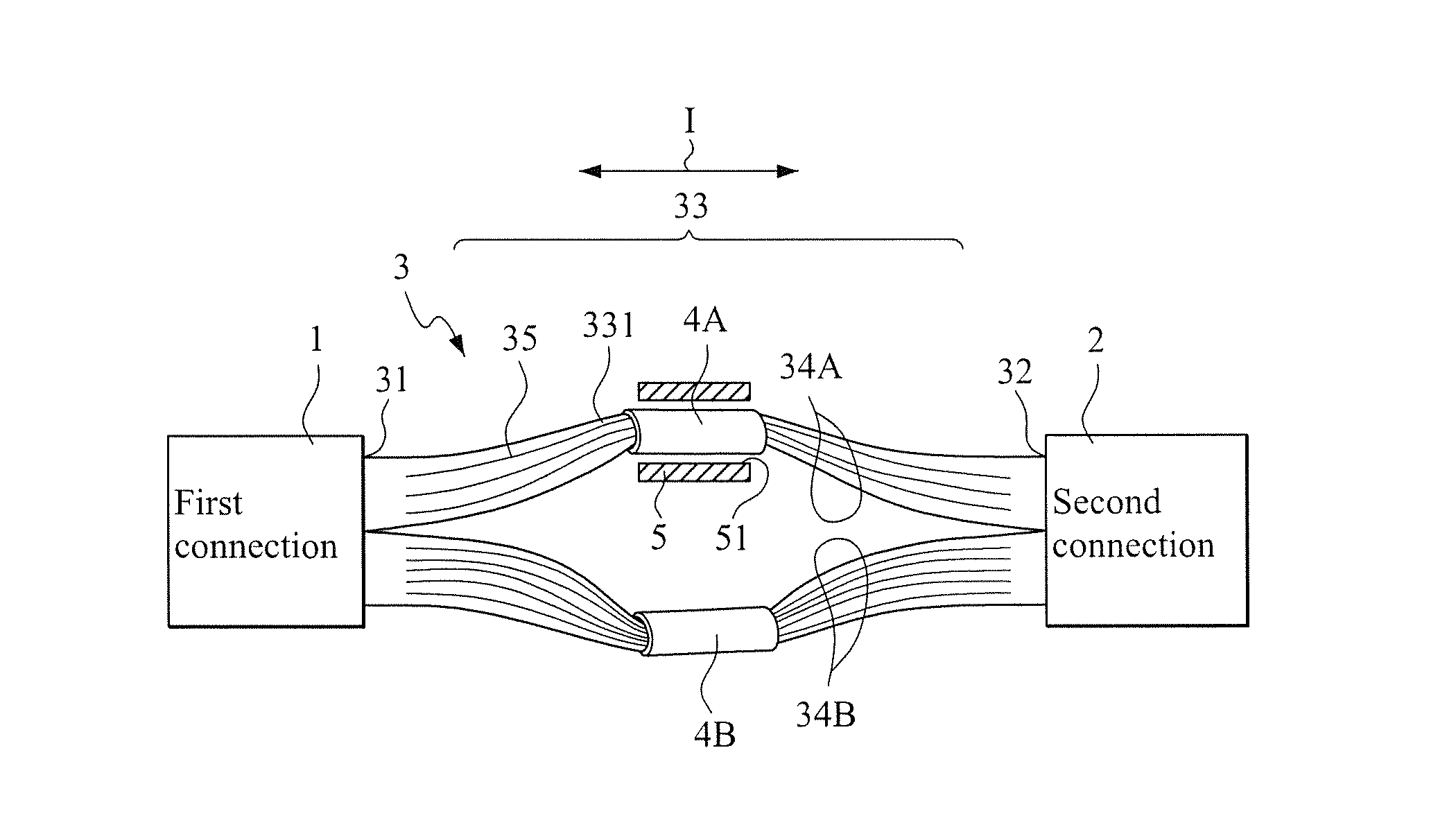
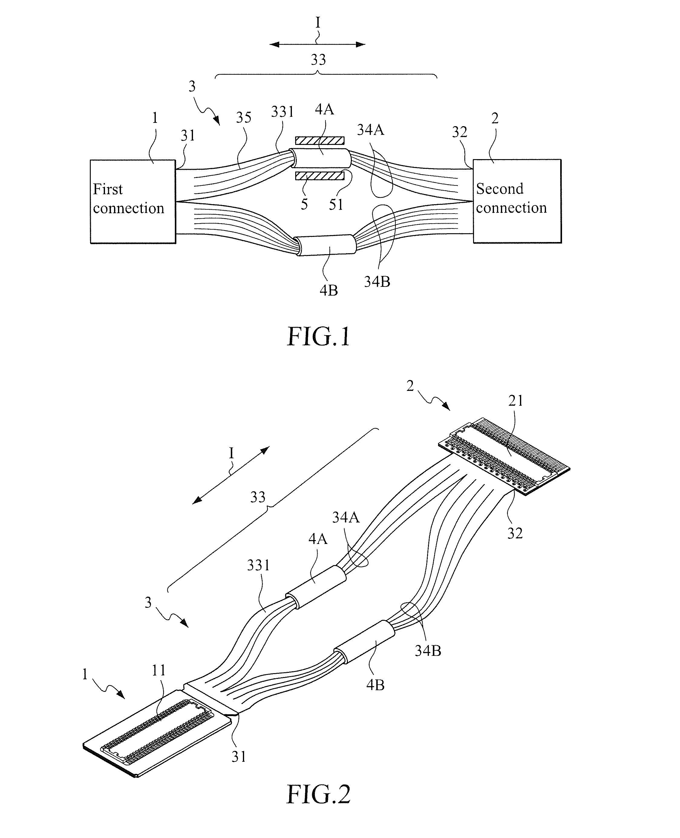
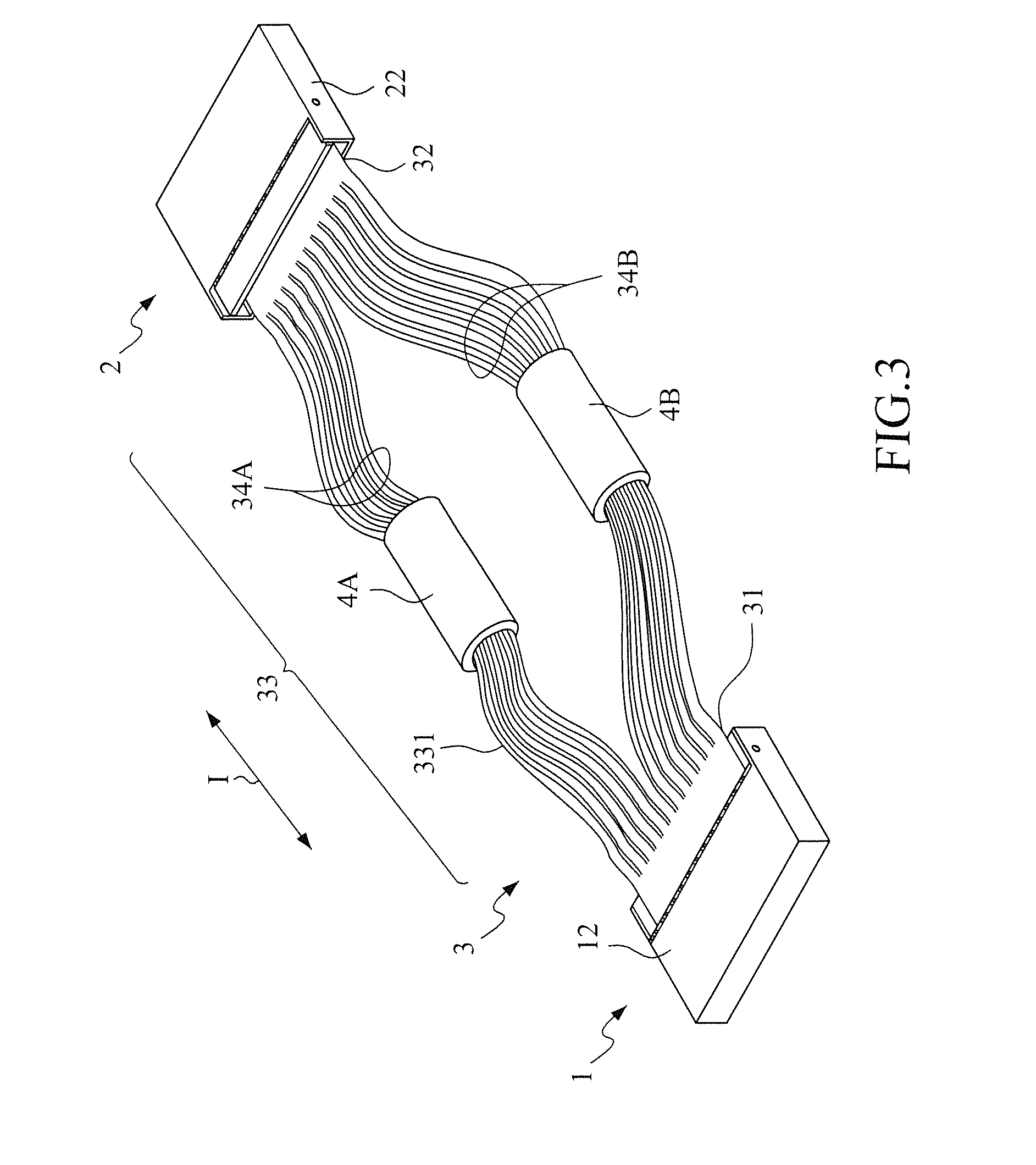
[0023]With reference to the drawings and in particular to FIG. 1, which is a schematic view showing a flexible circuit cable with at least two bundled wire groups constructed in accordance with the present invention, a flexible circuit cable according to the present invention comprises a first connection section 1, a second connection section 2, a circuit cable 33, and at least two bundling members 4A, 4B.

[0024]The first connection section 1 and the second connection section 2 can be made in the form of a plug terminal, a socket, a soldering terminal, an open terminal, or a composition mounting zone according to practical applications. As shown in FIG. 2, the first connection section 1 forms a component mounting zone, which has a surface forming a component mounting zone 11 where a connector can be mounted. The component mounting zone can be arranged in the direction shown in the drawing, or an arrangement by rotating 90 degrees is also feasible. The second connection section 2 may ...


PUM

PropertyMeasurementUnit
flexibleaaaaaaaaaa
electricalaaaaaaaaaa
frequencyaaaaaaaaaa

Abstract

Disclosed is a flexible circuit cable with at least two bundled wire groups. The circuit cable has first and second ends respectively connected to first and second connection sections. The circuit cable includes a cluster section, which is formed of a plurality of cluster wires formed by slitting the circuit cable, in an extension direction of the cable, at a predetermined cut width. The cluster section includes at least two independent bundles, which are formed by dividing the cluster wires of the circuit cable into different signal groups according to electrical signals transmitted therethrough. Bundling members are used to the cluster wires of the independent bundles according to predetermined bundling modes. Further, the circuit cable has a surface forming a shielding conductive layer for electromagnetic interference protection and impedance control for internal signals of the circuit cable.

Description

BACKGROUND OF THE INVENTION[0001]1. Field of the Invention[0002]The present invention relates to the structure of signal transmission cable, and in particular to a flexible circuit cable with at least two bundled wire groups.[0003]2. The Related Arts[0004]In various modern electronic devices, since the amount of data transmitted through signal lines is getting larger and larger, the number of signal lines used must be more and more and the frequency with which signals are transmitted must be higher and higher. Consequently, a differential mode of high frequency transmission is commonly adopted to reduce electromagnetic interference (EMI). For example, such a transmission technique is widely applied to USB or LVDS signals to reduce EMI. However, after the assembling of the signal transmission lines is completed, these signal transmission lines are often bundled for, on the one hand, positioning and, on the other hand, protection. The conventionally adopted signal transmission line bu...

Claims


Application Information

Patent Timeline
Patent Type & Authority Patents(United States)
IPC IPC(8): H01B7/00
CPCH05K2201/09663H05K2201/10356H05K1/0219H05K1/148H05K2201/09063H05K1/0218H05K1/028H05K2201/051H05K2201/055H01B7/04H01B11/00
Inventor LIN, GWUN, JIN
Owner ADVANCED FLEXIBLE CIRCUITS
Why Eureka
Try Eureka