Printing device using stamping

a printing device and stamping technology, applied in the field of printing devices using stamping, can solve the problems of inability to ensure optimal transport of sheets by gripper bars, natural tendency of polyester backing strips to stick to sheets, and disadvantages of entanglement of gripper bars

Active Publication Date: 2014-11-11
BOBST MEX SA
View PDF9 Cites 7 Cited by
  • Summary
  • Abstract
  • Description
  • Claims
  • Application Information

AI Technical Summary

Benefits of technology

[0011]Hence, the technical problem that the subject of the present invention attempts to solve is that of proposing a printing device for printing elements in sheet form, comprising a platen press for depositing onto each sheet, by stamping, colored or metalized film from at least one stamping foil, conveyor means using a succession of gripper bars for mov

Problems solved by technology

In practice though, it is unfortunately found that, when the platen press is reopened after stamping, the various polyester backing strips have a natural tendency to remain stuck to the sheet.
Such an arrangement does, however, have the disadvantage of entailing the use of gripper bars fitted with grippers at the top, that is to say with grippers which are

Method used


Image

  • Printing device using stamping
  • Printing device using stamping
  • Printing device using stamping

Examples


Embodiment Construction

[0029]For the sake of clarity, the same elements have been denoted by identical references. Likewise, only elements essential for understanding the invention have been depicted, and then only schematically and not to scale.

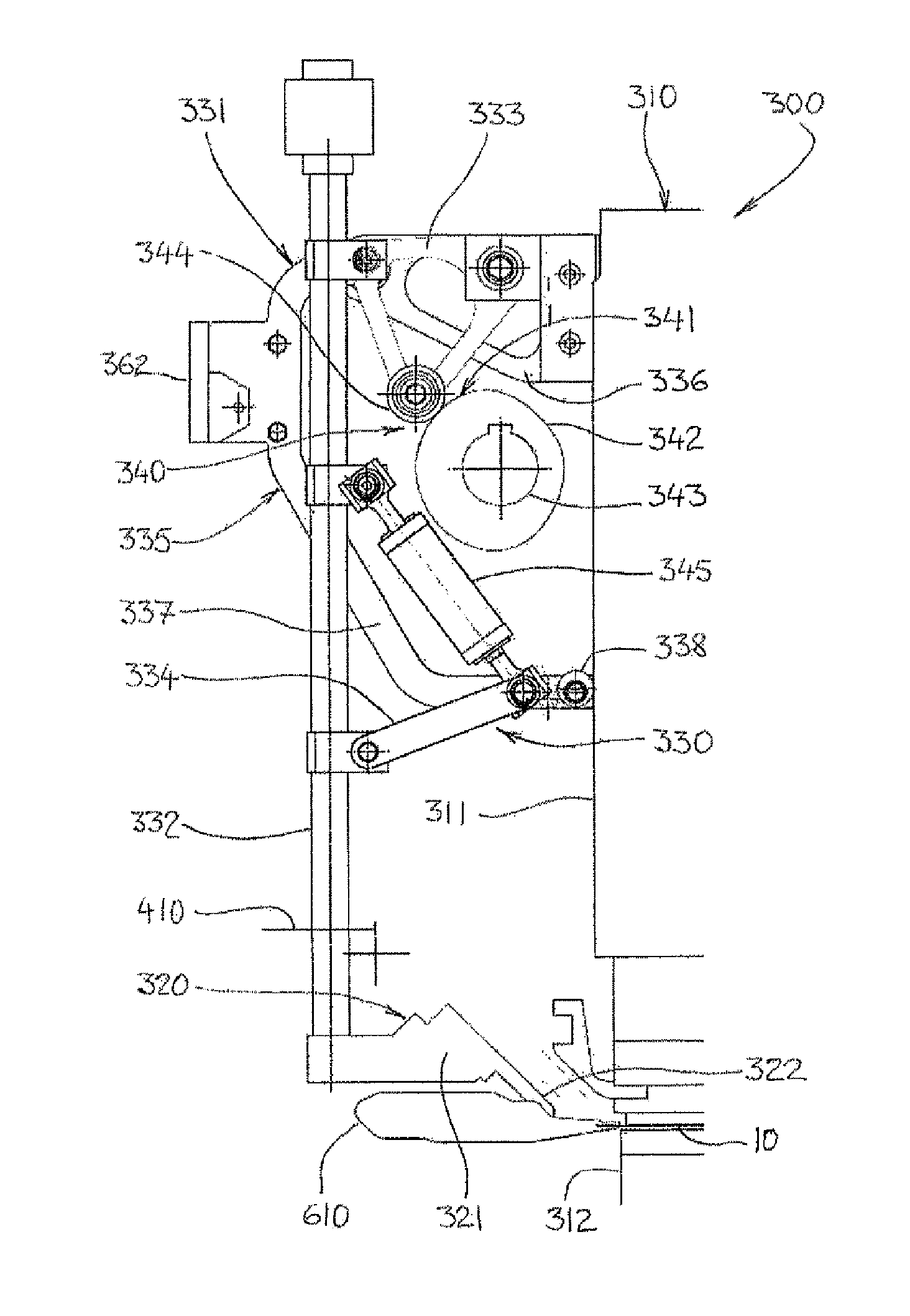
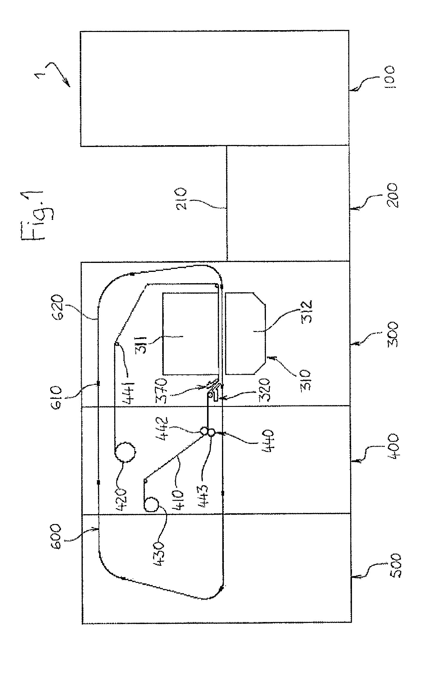
[0030]FIG. 1 depicts a stamping machine 1 which is intended for customizing cardboard packaging for the luxury goods industry. Commonly known as a gilding machine, this stamping machine 1 is conventionally made up of a number of work stations 100, 200, 300, 400, 500 which are juxtaposed with, but interdependent on, one another in order to form a unit assembly capable of processing a series of supports 10, 20 in sheet form. There is thus a feeder 100, a feed table 200, a printing device 300, a foil feed and recovery station 400, and a delivery station 500. Conveyor means 600 are also provided to move each sheet 10, 20 along individually from the exit of the feed table 200 to the delivery station 500, including through the printing device 300.

[0031]The various parts...


PUM

PropertyMeasurementUnit
Distanceaaaaaaaaaa
Mobilityaaaaaaaaaa

Abstract

A printing device for printing elements in sheet fond: a platen press 310 for depositing onto each sheet 10, by stamping, colored or metalized film from at least one stamping foil; a conveyor using a succession of gripper bars for moving each sheet 10 individually through the platen press 310; a blower member separates each stamping foil from each sheet as it leaves the platen press, the blower member being movable between a work position, in which it is able to operate from the transfer region in which the gripper bars 610 run to the exit of the platen press 310, and a withdrawn position, in which it keeps away from said transfer region.

Description

CROSS-REFERENCE TO RELATED APPLICATIONS[0001]The present application is a 35 U.S.C. §§371 national phase conversion of PCT / EP2011, filed Aug. 30, 2011, which claims priority of European Application No. 10009662.7, filed Sep. 16, 2010, the contents of which are incorporated by reference herein. The PCT International Application was published in the French language.BACKGROUND OF THE INVENTION[0002]The present invention relates to a device that allows elements in sheet form to be printed using stamping.[0003]The invention finds a particularly advantageous, although non-exclusive, application in the field of the manufacture of packaging intended for the luxury-goods industry.[0004]It is known practice for texts and / or patterns to be printed by stamping, that is to say by using pressure to apply to a medium in sheet form, colored or metalized film taken from one or more stamping foils commonly known as metalized foils. In the industry, such a transfer operation is usually performed using...

Claims


Application Information

Patent Timeline
IPC IPC(8): B65H29/56B41F1/38B41D7/00B41F1/32B65H29/04B41F1/12B41F1/44B41F1/30B41F16/00B41F19/02B31B50/88
CPCB41F1/38B41F1/44B41F1/30B41F16/0093B65H29/56B41F1/32B41F1/12B65H2406/122B65H29/044B65H2701/176B41F19/06B41F16/00
Inventor DE, GAILLANDE, CHRISTOPHE
Owner BOBST MEX SA
Why Eureka
Try Eureka