
Nerve cuff with pocket for leadless stimulator

a technology of neural stimulators and cuffs, which is applied in the field of implantable neural stimulators, can solve the problems of difficult and/or time-consuming system implanting, difficult to stably position the device in the proper position in relation to the nerve, and easy mechanical damage, so as to prevent nerve pinching

Active Publication Date: 2014-11-11
SETPOINT MEDICAL CORP
View PDF532 Cites 143 Cited by
  • Summary
  • Abstract
  • Description
  • Claims
  • Application Information

AI Technical Summary

Benefits of technology

The patent text describes the use of leadless cuffs with a microstimulator for improved results. These leadless cuffs have several advantages, including decreased encapsulation and the ability to securely attach to a nerve and hold the microstimulator in position. This allows for easy replacement or modification of the microstimulator without needing to move the entire system. In some variations, the channel is designed to support the nerve to prevent pinching. Overall, this technology provides improved outcomes and flexibility in stimulation programming.

Problems solved by technology

However, these systems can be difficult and / or time consuming to implant, as the electrodes and the IPG are usually implanted in separate areas and therefore the lead must be tunneled through body tissue to connect the IPG to the electrodes.
Also, leads are susceptible to mechanical damage over time as they are typically thin and long.
However, the leadless integral devices tend to be larger and more massive than the electrode / lead assemblies, making it difficult to stably position the device in the proper position in respect to a nerve.
Without device stability, the nerve and / or surrounding muscle or tissue can be damaged due to movement of the assembly.

Method used


Image

  • Nerve cuff with pocket for leadless stimulator
  • Nerve cuff with pocket for leadless stimulator
  • Nerve cuff with pocket for leadless stimulator

Examples


Embodiment Construction

[0064]Embodiments of the invention are directed to a retaining device, such as a carrier or cuff, which positions active contacts, i.e. electrodes, of a stimulation device against the targeted nerve directing the current from the electrodes into the nerve. The retaining device also inhibits or prevents the current from flowing out to the surrounding tissue.

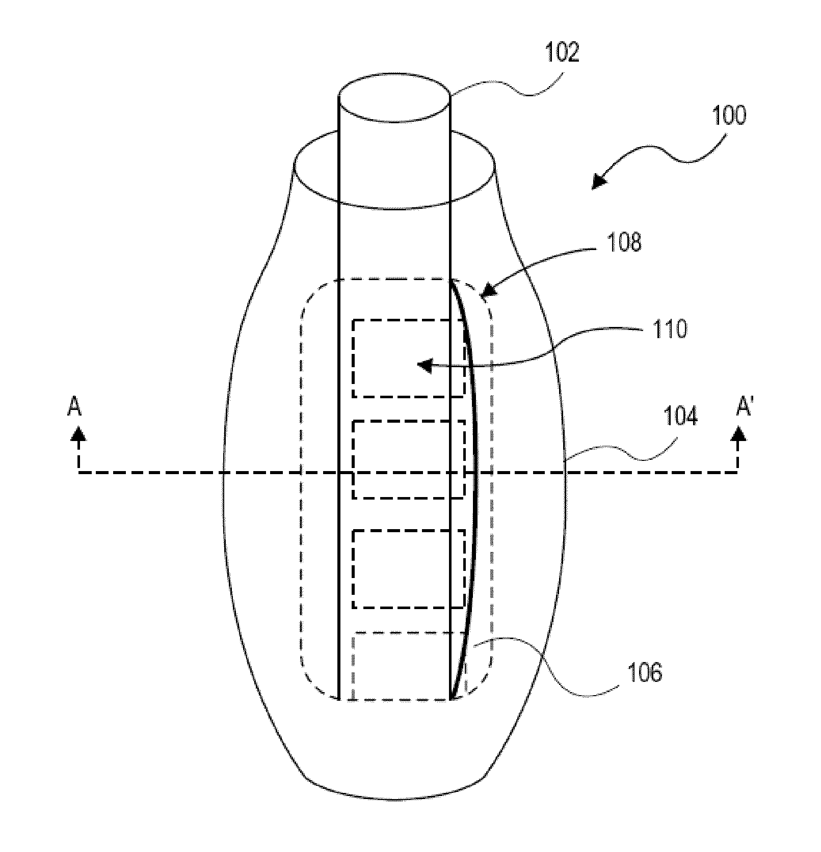
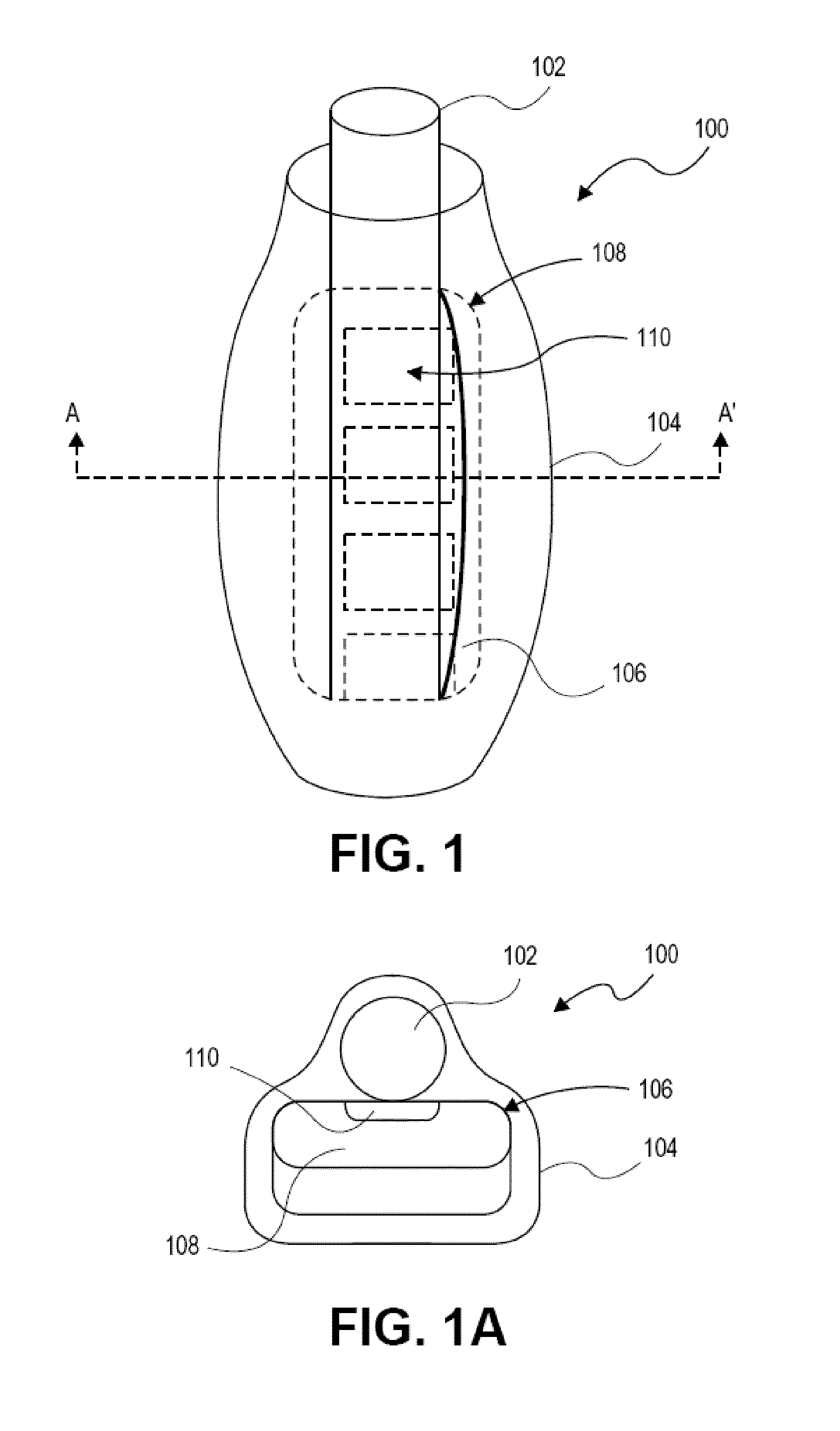
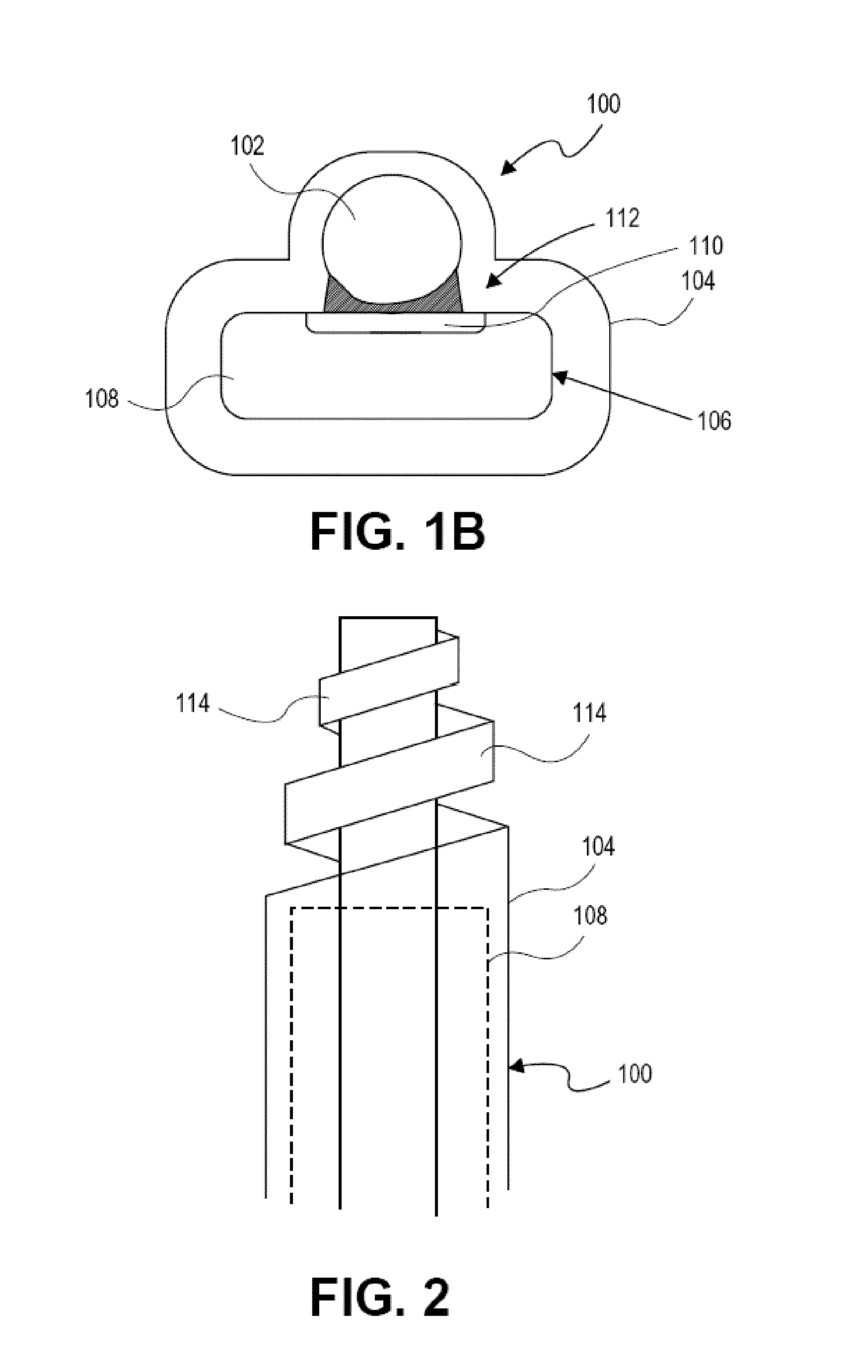
[0065]Referring to FIG. 1, one example of a nerve cuff 100 adapted for holding a stimulation device is coupled to a nerve 102. Nerve 102 can comprise any nerve in the human body targeted for therapeutic treatment, such as, for example, the vagus nerve. Nerve cuff adapter 100 generally comprises an outer carrier or cuff 104 body that can comprise any of a variety of medical grade materials, such as, for example, Silastic™ brand silicone elastomers, or Tecothane™ polymer.

[0066]In general, a nerve cuff including a cuff 104 body having (or forming) a pouch or pocket 106 for removably receiving an active, implantable stimulation device...


PUM


Abstract

An extravascular nerve cuff that is configured to hold a leadless, integral, implantable microstimulator. The nerve cuff may include a cuff body having a pocket or pouch for removably receiving the implantable device within. The nerve cuff can be secured around the nerve such that the electrodes of the device are stably positioned relative to the nerve. Furthermore, the nerve cuff drives the majority of the current from the stimulation device into the nerve, while shielding surrounding tissues from unwanted stimulation.

Description

CROSS REFERENCE TO RELATED APPLICATION[0001]This application claims the benefit under 35 U.S.C. §119 of U.S. Provisional Patent Application No. 61 / 185,494, filed on Jun. 9, 2009, titled “NERVE CUFF WITH POCKET FOR LEADLESS STIMULATOR”.INCORPORATION BY REFERENCE[0002]All publications and patent applications mentioned in this specification are herein incorporated by reference to the same extent as if each individual publication or patent application was specifically and individually indicated to be incorporated by reference.FIELD OF THE INVENTION[0003]The present invention relates generally to implantable neural stimulators, and more specifically to a nerve cuff with a pocket for removably receiving an active leadless stimulation device, and methods of stimulating a nerve using such nerve cuff.BACKGROUND OF THE INVENTION[0004]Implantable electrical stimulation devices have been developed for therapeutic treatment of a wide variety of diseases and disorders. For example, implantable ca...

Claims


Application Information

Patent Timeline
Patent Type & Authority Patents(United States)
IPC IPC(8): A61N1/05A61N1/36A61N1/375A61N1/372
CPCA61N1/0558A61N1/36114A61N1/37205A61N1/3756A61N1/375A61N1/0556A61N1/37518
Inventor FALTYS, MICHAEL A.MARTIN, ROY C.SCOTT, STEVEN E.LOEB, GERALD E.
Owner SETPOINT MEDICAL CORP
Learn More