
Integrated cavity type conductive fluid heat spreader

A conductive fluid and expander technology, which is applied in the field of thermal expanders, can solve the problems of high filling volume of precious metal fluid, limited space size, and reduced practicability, so as to achieve enhanced heat transfer and flow effects, reduce manufacturing and packaging procedures, Avoid the effects of fluid leakage and encapsulation

Active Publication Date: 2014-10-29
TECHNICAL INST OF PHYSICS & CHEMISTRY - CHINESE ACAD OF SCI
View PDF4 Cites 7 Cited by
  • Summary
  • Abstract
  • Description
  • Claims
  • Application Information

AI Technical Summary

Problems solved by technology

This structure shows much superior performance than the water-cooled radiator driven by a mechanical pump, but it also has a series of deficiencies, mainly including: 1. Only the position of the heat sink accounts for a small part of the total liquid metal filling in the entire circulation channel The fluid in the liquid can directly absorb heat, while the rest flows and transmits heat in the external pipe, so it is far from the efficient heat absorption capacity of liquid metal; 2. The fluid transmission channel is too long, and the filling amount of precious metal fluid is large, thereby increasing heat dissipation 3. The traditional liquid metal electromagnetic pump is an external type, arranged on a pipeline far away from the heat sink, and the magnet is placed outside the flow channel. The magnetic gap is large and the magnetic field is weak, so the driving force is limited; 4. Due to the limited space and small diameter of the flow channel in the traditional liquid metal radiator, the parallel distance between the electrode pairs arranged in it is small, so the power load is small, and the driving force is also low; 5. In particular, due to The pump body involves structures such as electrodes, pump bodies, pipes, magnets, seals, and substrates. There are many procedures and complicated manufacturing processes, and the fluid is easy to leak from the gaps. There are extremely high requirements in terms of leakage; 6. In addition, due to the introduction of multiple pipelines, special sealing boxes need to be added to fix the connections of various parts, especially in order to avoid fluid leakage. In the electromagnetically driven liquid metal radiator, since the heat sink, pipeline and electromagnetic pump body are designed, manufactured and connected separately, it is easy to cause some cavities in the circulation channel to appear dead angles that cannot be filled with liquid metal. It will cause the electrode pair not to be in contact with the metal fluid in some cases during operation, and even cause the circuit to be disconnected, and then the heat dissipation will be interrupted and the work of the chip will deteriorate.

Method used


Image

  • Integrated cavity type conductive fluid heat spreader
  • Integrated cavity type conductive fluid heat spreader
  • Integrated cavity type conductive fluid heat spreader

Examples


Embodiment 1

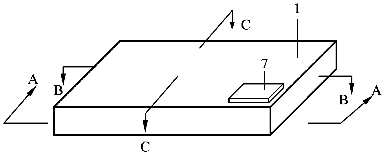
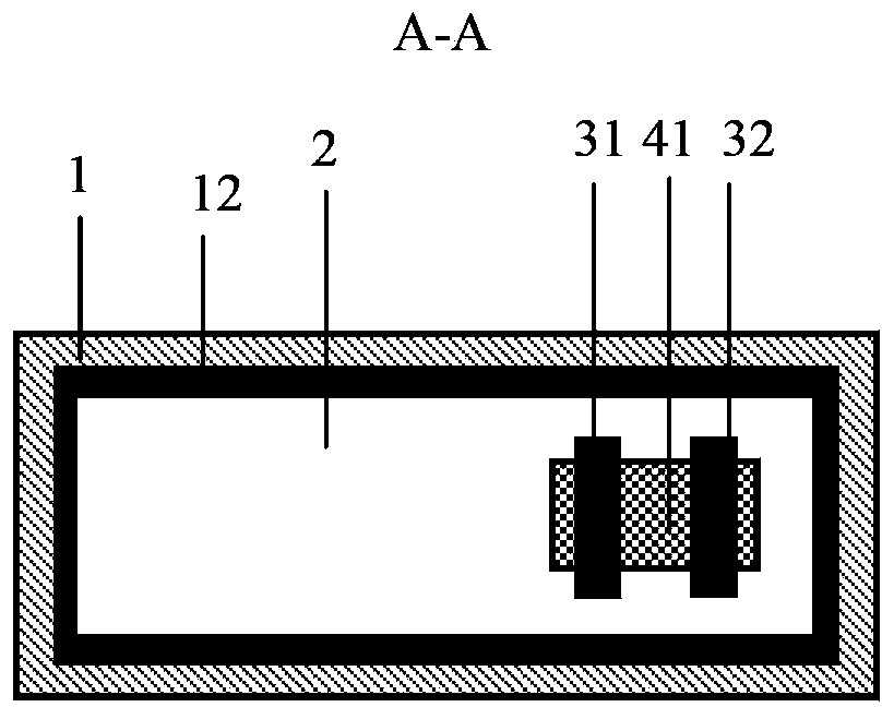
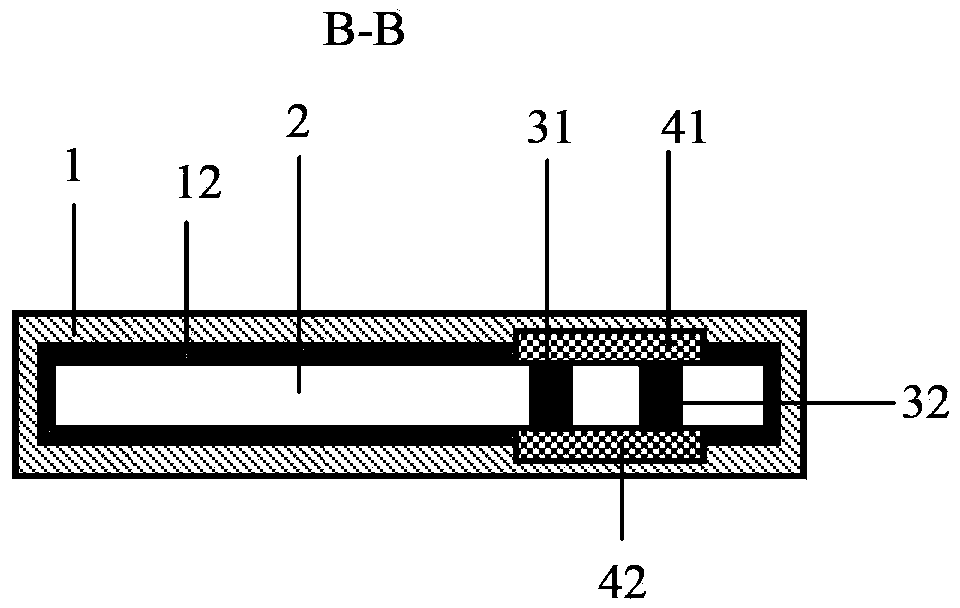
[0062] figure 1 It is a schematic diagram of the appearance of the integrated electromagnetic-driven cavity-type conductive fluid heat expander of the present invention (also a schematic structural diagram of an embodiment); figure 2 for figure 1 Schematic diagram of the A-A section (planar cross-section); image 3 for figure 1 Schematic diagram of the B-B section (longitudinal cross-section); Figure 4 for figure 1 Schematic of the C-C profile (transverse cross-section). As shown in the figure, the integrated electromagnetically driven cavity type conductive fluid heat expander of the present invention includes:

[0063] A cavity 1 with a thin-walled hollow structure inside, the heat-absorbing end, the flow channel, the liquid, the driving pump, the fluid pool and the heat-dissipating end are combined into one to form a cavity; thus a blade-type heat expander can be formed;

[0064] When the material of the cavity 1 is metal, its inner surface is an insulating layer 12...

Embodiment 2

[0076] Figure 5 It is a schematic diagram of the appearance of an integrated electromagnetically driven cavity-type conductive fluid heat spreader with ribs 13 on one side of the present invention; hot. All the other structures are identical to Example 1.

Embodiment 3

[0078] Image 6 It is a schematic diagram of the appearance of an integrated electromagnetically driven cavity-type conductive fluid thermal expander with ribs on both sides of the cavity of the present invention; to enhance heat transfer. All the other structures are identical to Example 1.


PUM


Abstract

The invention provides an integrated cavity type conductive fluid heat spreader which includes a cavity (1), the heat absorbing end, flow, liquid, fluid pool, driving pump and a heat radiating end together in one room, the internal cavity structure, and the inner surface is an insulating layer (12); runner type electrode for (31, 32), arranged on the cavity surface, which is used as a channel and the direction of fluid flow regulator; a magnet for (41, 42), in the cavity body and the direction of the magnetic poles and the electrode is arranged on the current direction is vertical range setting; conductive fluid (2), the filling in the cavity; power supply chip (7) which is arranged in the cavity, the outer surface of the electrodes used to provide the input current. According to the heat spreader is provided by the invention greatly reduces the production and packaging process, completely avoid the fluid leakage; the compact volume, heat transfer capacity significantly; the cavity electrode on the position can be set flexibly, significantly enhance the electromagnetic driving force, resulting in the enhancement of heat transfer and flow effect is strong; between different parts of the body temperature of the fluid cavity different mixing efficiency is high, the heat transport capability is strong.

Description

technical field [0001] The invention relates to the technical field of thermal expanders, in particular to an integrated cavity-type conductive fluid thermal expander driven by electromagnetic force and without an external flow channel. Background technique [0002] At present, optoelectronic devices, which are widely used in industries such as information, energy, optoelectronics, space applications, weapon systems, and power electronics, have increasingly serious heat dissipation problems due to the increase in integration. Efficient and reliable cooling and thermal management technologies are indispensable here. Due to the low calorific value and low heat flux density of early optoelectronic devices, conventional air cooling can meet the requirements. In recent years, with the rapid development of micro-nano electronic processing technology, the integration of various computer chips and optoelectronic devices has reached an unprecedented level. Therefore, the industry g...

Claims


Application Information

Patent Timeline
Patent Type & Authority Applications(China)
IPC IPC(8): H05K7/20
Inventor 刘静
Owner TECHNICAL INST OF PHYSICS & CHEMISTRY - CHINESE ACAD OF SCI
Learn More