
Extended connectivity point-of-deployment apparatus and concomitant method thereof

a point-of-deployment and connectivity technology, applied in the field of point-of-deployment (pod) modules, can solve the problems of imposing constraints and conditions on recording and playback, impeded their widespread use, and one-way cablecards deployed in the united states, and do not provide interactive program guides, video on demand control functions,

Active Publication Date: 2014-11-11
SYNDEFENSE
View PDF8 Cites 235 Cited by
  • Summary
  • Abstract
  • Description
  • Claims
  • Application Information

AI Technical Summary

Benefits of technology

This patent is about a new way to securely transmit media content from a wireless device to other devices. The device also has a storage unit that allows for real-time viewing and listening of broadcasts, as well as the ability to quickly jump to previous segments. The device can also register wireless VoIP handsets using RFID.

Problems solved by technology

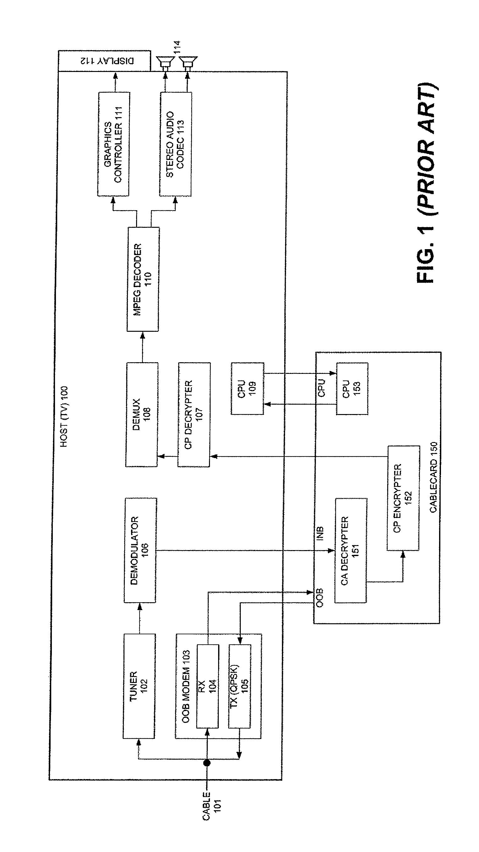
CableCARDs are designed to descramble scrambled content into a clear format for viewing and / or listening, and may impose constraints and conditions on the recording and playback when the content is copy-protected through re-scrambling as it flows back to the host device.
While POD modules obviate the need for STTs that perform the same functions described above, the current generation of POD modules has several limitations, which have impeded their widespread use.
For example, the current generation of CableCARDs deployed in the United States are one-way and do not provide for an Interactive Program Guide, Video on Demand control functions, interactive and enhanced services, pay-per-view, and other capabilities.
While two-way CableCARDs have been developed and should provide some of these features in the future, there exists a backward compatibility problem with existing host devices that only support one-way CableCARD modules.
Even with the newer CableCARDs that support two-way communication, consumers are still faced with having to purchase multiple media devices in order to satisfy their entertainment needs.
These devices tend to be expensive and take valuable real estate within the home.
A problem remains in getting personal computers to communicate with television sets.
Often, the two devices do not have compatible connectors to allow for direct connectivity.
When compatible connector types are available, such connectivity methods are limiting in that the personal computer must be tethered to the television while communicating.
Even if the devices can be connected while in different rooms, there is generally no way to remotely control the personal computer.
Such STTs can be expensive and often provide functionality that overlaps with personal computers.
Unfortunately, a large base of installed digital televisions and those being sold on the market today do not provide for either wireless or wireline access to a data network.
As described above, CableCARDs are one-way and do not provide for an Interactive Program Guide, Video on Demand control functions, interactive and enhanced services, pay-per-view, and other capabilities.
Although two-way CableCARDs have been developed to provide some of the above features, a backward compatibility problem exists in that the host devices support only one-way CableCARD modules.
Even with a newer CableCARD that supports two-way communication, consumers are still faced with having to purchase multiple STTs that provide digital video recording and playback, multimedia time shifting, gaming, Internet downloading, and a remote access to digital content stored on network-connected media player devices such as personal computers and the like.
However, a conventional POD module cannot properly communicate with other personal electronic devices, such as personal digital assistants (PDAs), cellular phones, music players, video players, game players, etc.

Method used


Image

  • Extended connectivity point-of-deployment apparatus and concomitant method thereof
  • Extended connectivity point-of-deployment apparatus and concomitant method thereof
  • Extended connectivity point-of-deployment apparatus and concomitant method thereof

Examples


Embodiment Construction

[0072]Reference will now be made in detail to the embodiments of the present general inventive concept, examples of which are illustrated in the accompanying drawings, wherein like reference numerals refer to the like elements throughout. The embodiments are described below in order to explain the present general inventive concept by referring to the figures.

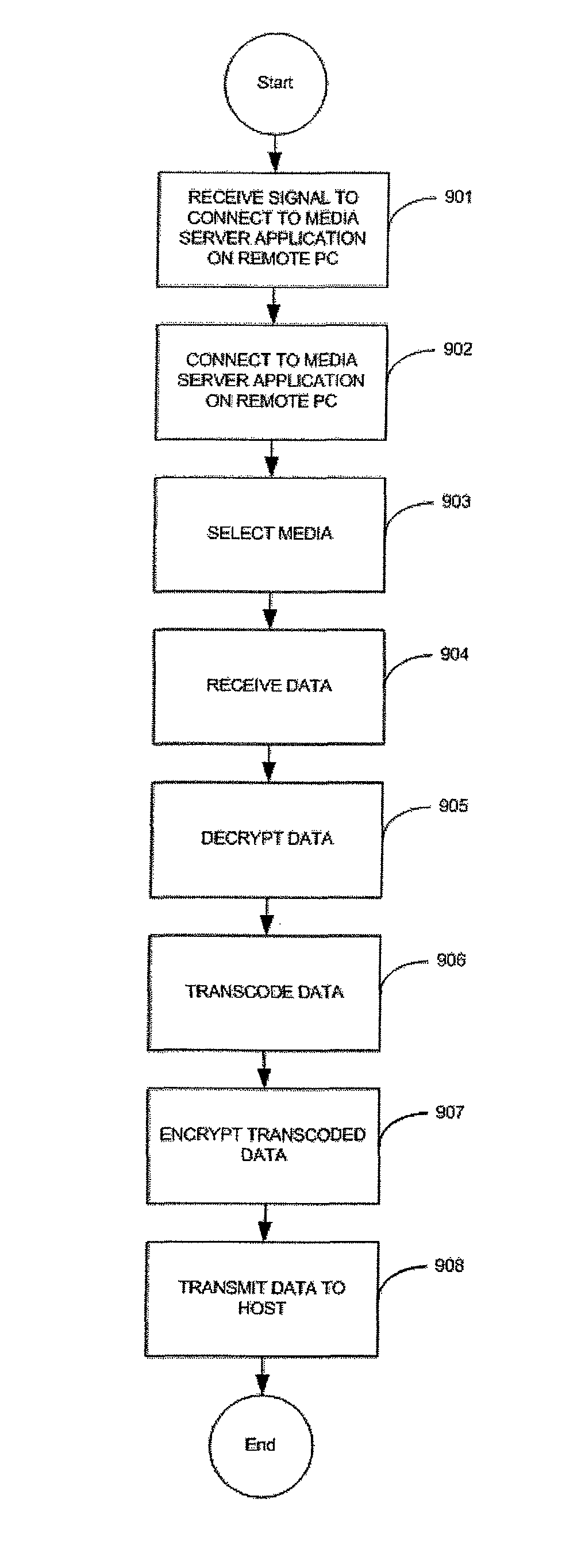
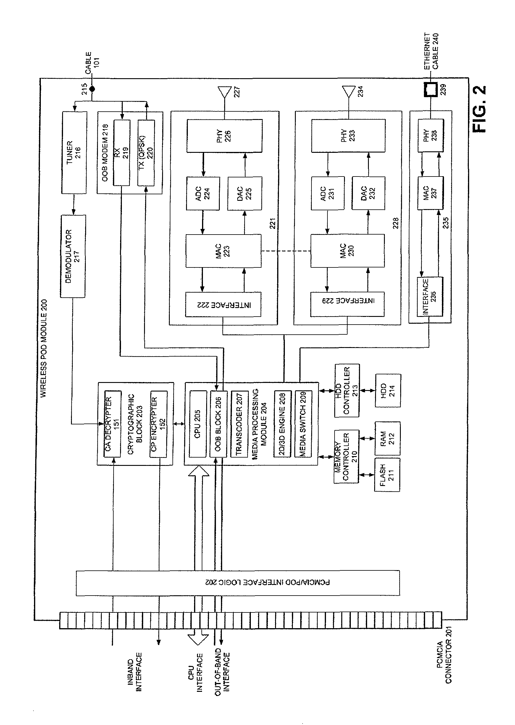
[0073]FIG. 2 is a block diagram illustrating components of a wireless point of deployment (POD) module 200 according to an embodiment of the present general inventive concept. A set-top terminal (STT) may not be necessary to operate a host (e.g., television) connectable to an external network through the wireless module 200. The present embodiment described herein applies equally to all types of POD modules, including, but not limited to CableCARDs and Common Interface Modules

[0074]Conditional Access (CA) devices, such as CableCARDs, are typically built in accordance with prescribed physical and electrical standards, to ensure c...


PUM


Abstract

A POD module system includes a housing, a coaxial cable connector formed on the housing and connectable to a first device to receive a cable signal, a port formed on the housing to receive a wire or wireless signal from a second device, a module unit to process at least one of the cable signal and the at least one of the wireless signal to generate at least one of a copy protection signal and one of video and audio signals, respectively, and a connector formed on the housing and connectable to a third device to transmit the at least one of the copy protection signal and the one of video and audio signals to the third device such that the third device generates at least one of an image and a sound to correspond to the at least one of the copy protection signal and the one of video and audio signals.

Description

CROSS-REFERENCE TO RELATED APPLICATIONS[0001]This application claims the benefit of U.S. Provisional Application No. 60 / 783,825 filed with United States Patent and Trademark Office on Mar. 21, 2006, the disclosure of which is incorporated herein in its entirety by reference.BACKGROUND OF THE INVENTION[0002]1. Field of the Invention[0003]The present general inventive concept relates to a point of deployment (POD) module and a method thereof. More specifically, the present general inventive concept relates to a wireless point of deployment (POD) module and a method thereof.[0004]2. Description of the Related Art[0005]Broadband communication systems, such as satellite and cable television systems, are now capable of providing many services in addition to broadcast video. In implementing enhanced programming, the set-top terminal (STT), otherwise known as a set-top box, has become an important computing device for accessing various video services. In addition to supporting traditional b...

Claims


Application Information

Patent Timeline
Patent Type & Authority Patents(United States)
IPC IPC(8): H04N7/167H04W12/06H04N7/173G06F15/16H04B7/00H04N21/2347H04N7/16H04H40/00H04W4/00H04N21/418H04L29/06H04N21/4405G06F21/00H04N21/4363H04B5/00G06F7/04H04K1/00H04N7/18H04W48/16
CPCH04N21/4183H04N21/4405H04N7/163H04N21/2347H04N21/43637H04L63/0471H04N21/4181H04L2209/805H04W48/16H04W12/06H04W4/00H04N21/47217G06F13/10H04W8/08H04N21/4363H04N21/2543H04N21/43635H04N21/42607H04N21/440218H04N21/42221H04N21/441H04N21/64322H04L65/60H04N21/4402H04N21/42206G06F13/4221G06Q20/14
Inventor DUA, ROBIN
Owner SYNDEFENSE
Learn More