Wafer check valve assembly and related methods of use

a check valve and assembly technology, applied in the direction of valve housings, functional valve types, transportation and packaging, etc., can solve the problems of wafer check valves being notoriously small in the flow port area, devices can typically only be used, and shortcomings of prior art designs

Active Publication Date: 2014-11-18
HAYWARD IND INC
View PDF9 Cites 10 Cited by
  • Summary
  • Abstract
  • Description
  • Claims
  • Application Information

AI Technical Summary

Benefits of technology

[0017]The present disclosure provides for improved flow control assemblies for fluid systems. More particularly, the present disclosure provides for advantageous wafer check valve assemblies for fluid systems (e.g., piping systems or the like). In exemplary embodiments, the present disclosure provides for advantageous wafer check valve assemblies that include an angled sealing surface, which allows the disc member to seal even with the valve assembly in the horizontal position, and / or to seal without the aid of a spring.
[0018]In general, angling the sealing surface allows the center of gravity of the disc member to be used for a mechanical advantage when the valve is installed in a horizontal orientation. With the valve installed in the horizontal orientation, the natural bias of the disc member is to drop down into the sealing surface. The center of gravity of the disc member in a free-hanging condition is inside of the angle of the sealing surface, so that the seal surface effectively catches the disc member before it is allowed to reach its gravitationally natural position, thus using the center of gravity of the disc member advantageously to affect a seal with the valve installed in a horizontal orientation.
[0027]The present disclosure also provides for a wafer check valve assembly wherein the third mating surface of the body member includes at least one pocket; wherein the sixth mating surface of the retainer member includes at least one alignment boss extending therefrom; and wherein when the body member and the retainer member are releasably mated together, at least a portion of the at least one alignment boss is positioned within at least a portion of the at least one pocket to facilitate proper alignment of the mated body member and retainer member, and to substantially prevent rotation of the retainer member relative to the body member.
[0028]The present disclosure also provides for a wafer check valve assembly wherein the shaft groove extends from a first end to a second end, the second end larger in diameter than the first end; wherein the shaft member of the disc member extends from a first end to a second end, the second end larger in diameter than the first end; wherein the first end of the shaft groove inhibits from being housed therein the larger second end of the shaft member; and wherein when the disc member is rotatably housed within at least a portion of the shaft groove, the first end of the shaft member is positioned within the first end of the shaft groove and the second end of the shaft member is positioned within the second end of the shaft groove to facilitate proper alignment of the disc member relative to the body member.
[0030]The present disclosure also provides for a wafer check valve assembly wherein the sixth mating surface of the retainer member includes at least one column member extending therefrom; and wherein when the body member, retainer member and disc member are releasably mated together, the at least one column member rotatably housing the shaft member between the body member and the retainer member and within at least a portion of the shaft groove, while substantially preventing the shaft member from moving in the lateral and axial directions.
[0031]The present disclosure also provides for a wafer check valve assembly wherein the sixth mating surface of the retainer member includes at least one rib member extending downwardly from the sixth mating surface toward the outlet opening, the at least one rib member including a first engagement surface; wherein the body portion of the disc member includes a rib member extending from a top surface, the disc member rib member including a second engagement surface; and wherein when the disc member is rotated to the open position, the engagement of the first and second engagement surfaces limits the travel of the disc member in the open position and substantially prevents contact between the disc member and an inside wall of a downstream pipe.

Problems solved by technology

In general, these devices can typically only be used where the shaft of the valve extends through the walls of the body of the valve.
There are several issues, flaws and / or shortcomings with prior art designs.
First, wafer check valves are generally notorious for their reduced flow port area (i.e., restricted flow).
Typically, if spacers are not used, the rotation of the disc may be restricted, which further restricts the flow of fluid through the valve.
The spacer is a general nuisance for several reasons: first, the requirement for spacers is often not anticipated nor understood by users; second, installation becomes more difficult, as another independent component must be handled and managed while attempting to install the valve and spacer between two flanges; third, the actual space in a system required to properly install wafer check valves (with spacers) is often underestimated, requiring last minute system design adjustments, sometimes additional cost, and / or compromising system performance by using the wafer check valve under less than ideal installation conditions (e.g., without a spacer), resulting in restricted flow in the system.
Moreover, installation of valves without spacers can result in the disc striking the inside wall of the adjoining flange or pipe.
This can result in restricted opening of the disc, as well as damage to the disc, and possibly even failure of the disc.
Furthermore and typically with respect to thermoplastic wafer check valves, the disc to shaft transition is often the weakest link of the valve, resulting in failure of the disc due to rapid flow reversal and the associated impact loading of the disc.
These methods typically rely, to some extent, on the proper assembly of the valve between the two adjoining flanges to assist the retention means, whereas, improper installation between the flanges (i.e., misalignment) can result in one, or both, of the retainers coming loose and allowing the disc to dislodge from the assembly.
Excessive torque, improper bolt tightening sequence, and / or misalignment can all result in deficiencies in valve performance.
When installed in piping systems that are horizontal, the disc component of these valves typically hangs straight down and generally cannot render any mechanical sealing advantage from gravitational forces, thereby typically requiring the assistance of a spring to return to the closed and seated position once flow in the system terminates.

Method used


Image

  • Wafer check valve assembly and related methods of use
  • Wafer check valve assembly and related methods of use
  • Wafer check valve assembly and related methods of use

Examples


Embodiment Construction

[0077]In the description which follows, like parts are marked throughout the specification and drawings with the same reference numerals, respectively.

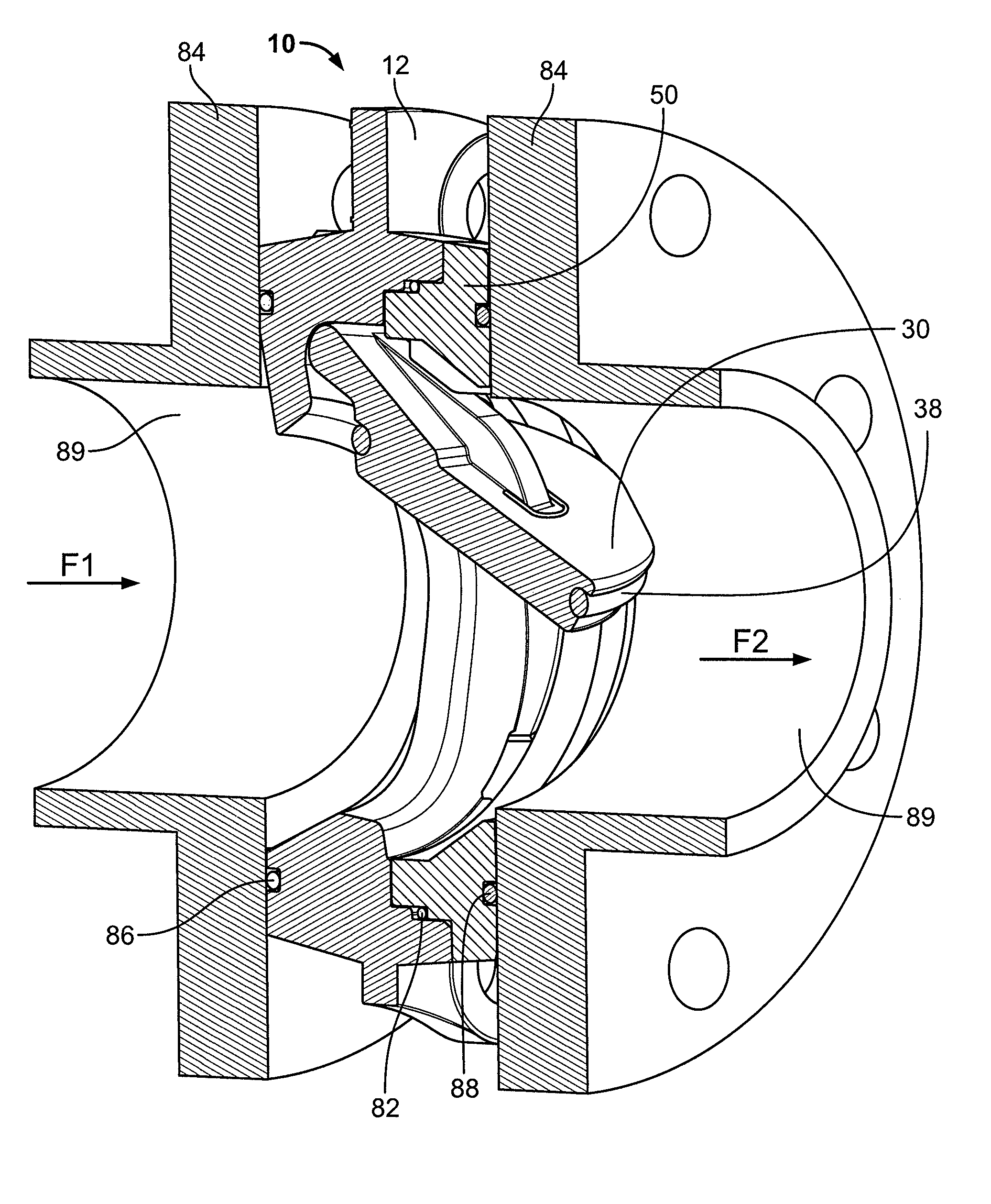
[0078]The present disclosure provides for advantageous flow control assemblies for fluid systems (e.g., industrial and / or commercial systems). More particularly, the present disclosure provides for convenient, low-cost and / or effective systems and methods for utilizing improved wafer check valve assemblies in fluid systems (e.g., piping systems or the like). In exemplary embodiments, the present disclosure provides for advantageous wafer check valve assemblies that include an angled sealing surface, which allows the disc member to seal even with the valve assembly in the horizontal position, and / or to seal without the aid of a spring.

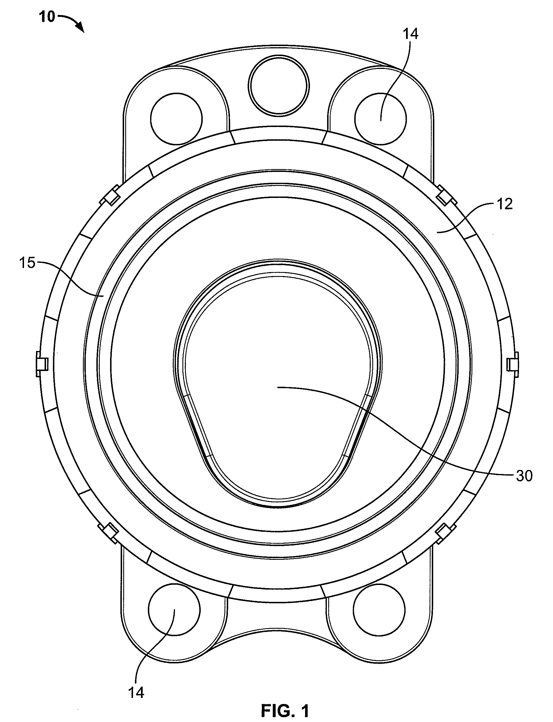
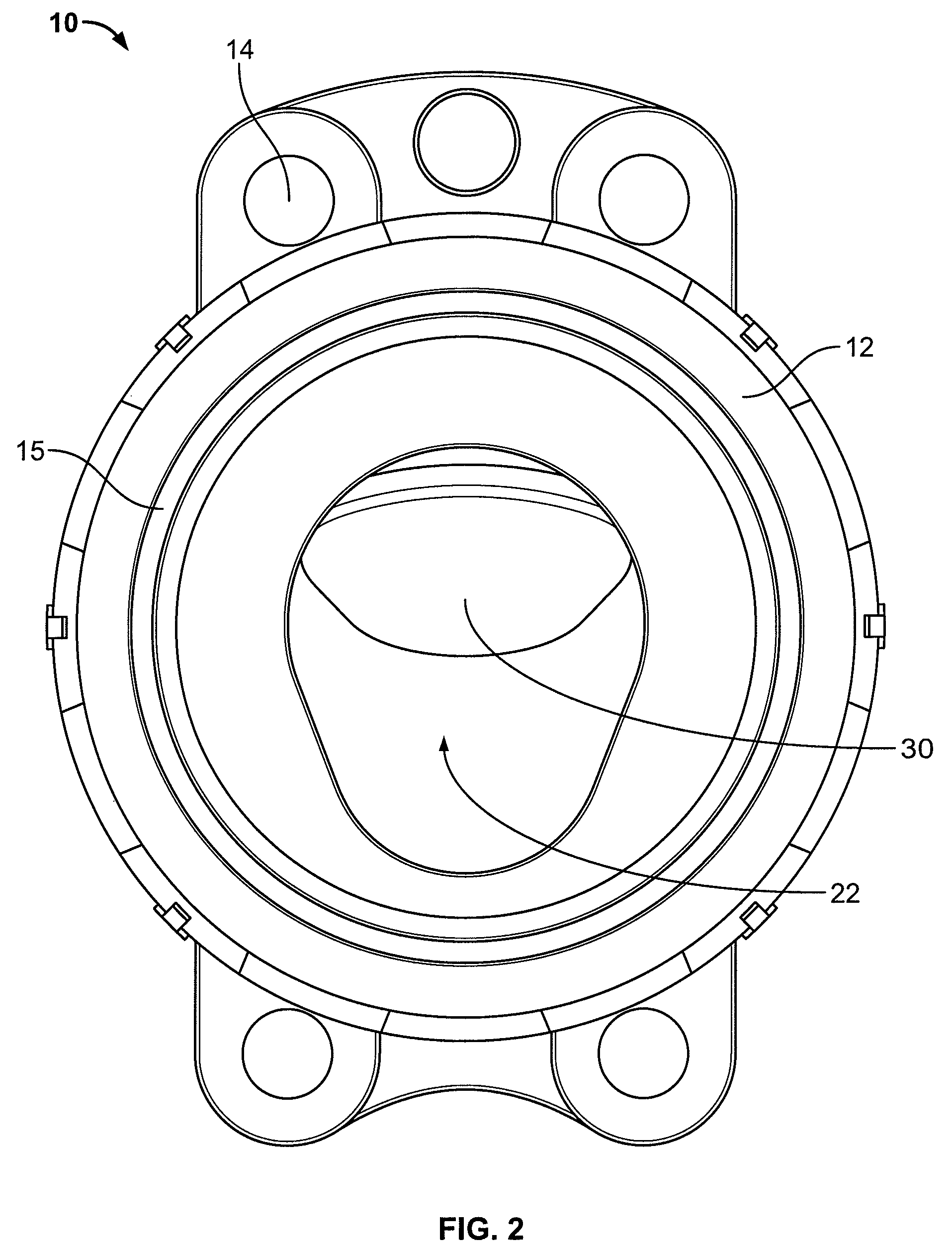
[0079]Referring now to the drawings, there is illustrated an exemplary wafer check valve assembly 10. Wafer check valve assembly 10 typically includes a body member 12, a retainer member or end ring membe...


PUM


Abstract

Provided is a wafer check valve assembly comprising a body having a mating side including first, second and third surfaces and a shaft groove, a tapered surface of the mating side extends from the third surface toward an inlet side of the body and from a first end to a second end of a port opening; a retainer having a mating side including fourth, fifth and sixth surfaces; and a disc with a shaft; wherein, when the body, retainer and disc are mated together: the shaft is housed between the body and the retainer and within the shaft groove, the first and fourth surfaces are proximal, the second and fifth surfaces are proximal, and the third and sixth surfaces proximal, so to define a pocket housing a gasketing material to form a seal between the body and retainer and to secure together the body, retainer, and disc.

Description

BACKGROUND[0001]1. Technical Field[0002]The present disclosure generally relates to flow control assemblies for fluid systems, and more particularly, to wafer check valve assemblies for piping systems.[0003]2. Background Art[0004]Flow control assemblies for use in fluid systems are known. For example, assemblies utilizing flow control devices (e.g., valves) in fluid systems (e.g., piping systems) have been developed. Flow control assemblies are useful in a myriad of different environments for commercial and industrial applications.[0005]In general, wafer check valves are a type of flow control device and usually include a body component, a disc or flapper component, a means to attach the disc component to the body component, and a seal or seat. These valves typically also include a hinge or shaft, which may be an integral feature of the disc component, or may be a separate component, which for example, is inserted through the disc component and allows the disc to rotate on the shaft...

Claims


Application Information

Patent Timeline
Patent Type & Authority Patents(United States)
IPC IPC(8): F16K15/00
CPCF16K15/033F16K27/0227F16K15/03Y10T137/7903Y10T137/7857Y10T137/7898
Inventor MOREN, GARY A.HOOTS, JOSHUA LEESTONE, JON TERENCEGUTMANN, PAUL M.
Owner HAYWARD IND INC
Why Eureka
Try Eureka