Over-running decoupler with torque limiter

a technology of torque limiter and over-running decoupler, which is applied in the direction of slip coupling, gearing, hoisting equipment, etc., can solve the problems of significant reduction of the operating life of the over-running decoupler, and achieve the effect of preventing resonance and reducing fatigue li

Active Publication Date: 2014-11-18
LITENS AUTOMOTIVE INC
View PDF42 Cites 35 Cited by
  • Summary
  • Abstract
  • Description
  • Claims
  • Application Information

AI Technical Summary

Benefits of technology

[0002]The present disclosure generally relates to drive systems in which rotary power is transmitted between a source of rotary power and one or more driven components and an over-running decoupler is employed to dampen fluctuations in the torsional load transmitted from the source of rotary power to the driven component, as well as to permit one or more of the driven components to be decoupled from and re-coupled to the source of rotary power to reduce or eliminate torsional loads occurring as a result of deceleration of the source of rotary power relative to the driven component. More particularly, the present disclosure relate to a method for inhibiting a resonant condition in an over-running decoupler.
[0003]It is known to provide an over-running decoupler in a drive system to permit one or more driven components in the drive system to decouple to reduce or eliminate torsional loads occurring as a result of the deceleration of a source of rotary power relative to the driven component. Exemplary over-running decouplers are disclosed in U.S. patent application Ser. Nos. 10 / 519,591, 10 / 542,625, 10 / 572,128 and 10 / 581,097 and employ Ser. Nos. 10 / 519,591, 10 / 542,625, 10 / 572,128 and 10 / 581,097 and employ a torsionally resilient coupling between a decoupler input member and a decoupler output member.
[0005]In one form, the present teachings provide a method for producing an over-running decoupler that is configured to transmit rotary power between a rotary member and a hub. The over-running decoupler includes a one-way clutch having a clutch spring, a carrier that is coupled to the clutch spring and at least one spring that resiliently couples the carrier to the hub. The method includes: establishing a desired fatigue life of the at least one spring; establishing a design deflection of the at least one spring during resonance, wherein deflection of the at least one spring at the design deflection during resonance does not reduce a fatigue life of the at least one spring below the desired fatigue life; and preventing resonance in the over-running decoupler by controlling a maximum deflection of the at least one spring such that the maximum deflection is less than or equal to the design deflection.
[0007]In a further form, the teaching of the present disclosure provide a method for producing an over-running decoupler that is configured to transmit rotary power between a rotary member and a hub. The over-running decoupler includes a clutch having a clutch spring, a carrier that is coupled to the clutch spring and at least one spring that resiliently couples the carrier to the hub. The method includes: establishing a desired fatigue life of the at least one spring; establishing a design torque that may be, transmitted through the at least one spring during resonance, wherein transmission of the design torque through the at least one spring during resonance does not reduce a fatigue life of the at least one spring below the desired fatigue life; and preventing resonance in the over-running decoupler by controlling a maximum torque transmitted through the decoupler such that the maximum torque is less than or equal to the design torque.

Problems solved by technology

We have noted that operation of an over-running decoupler under some load conditions can cause the torsionally resilient coupling of the over-running decoupler to vibrate at a natural frequency (i.e., resonate), which can significantly reduce the operating life of the over-running decoupler.

Method used


Image

  • Over-running decoupler with torque limiter
  • Over-running decoupler with torque limiter
  • Over-running decoupler with torque limiter

Examples


Embodiment Construction

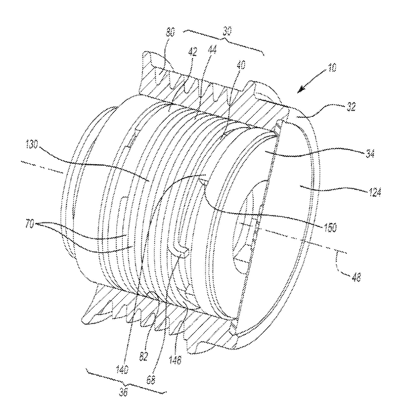
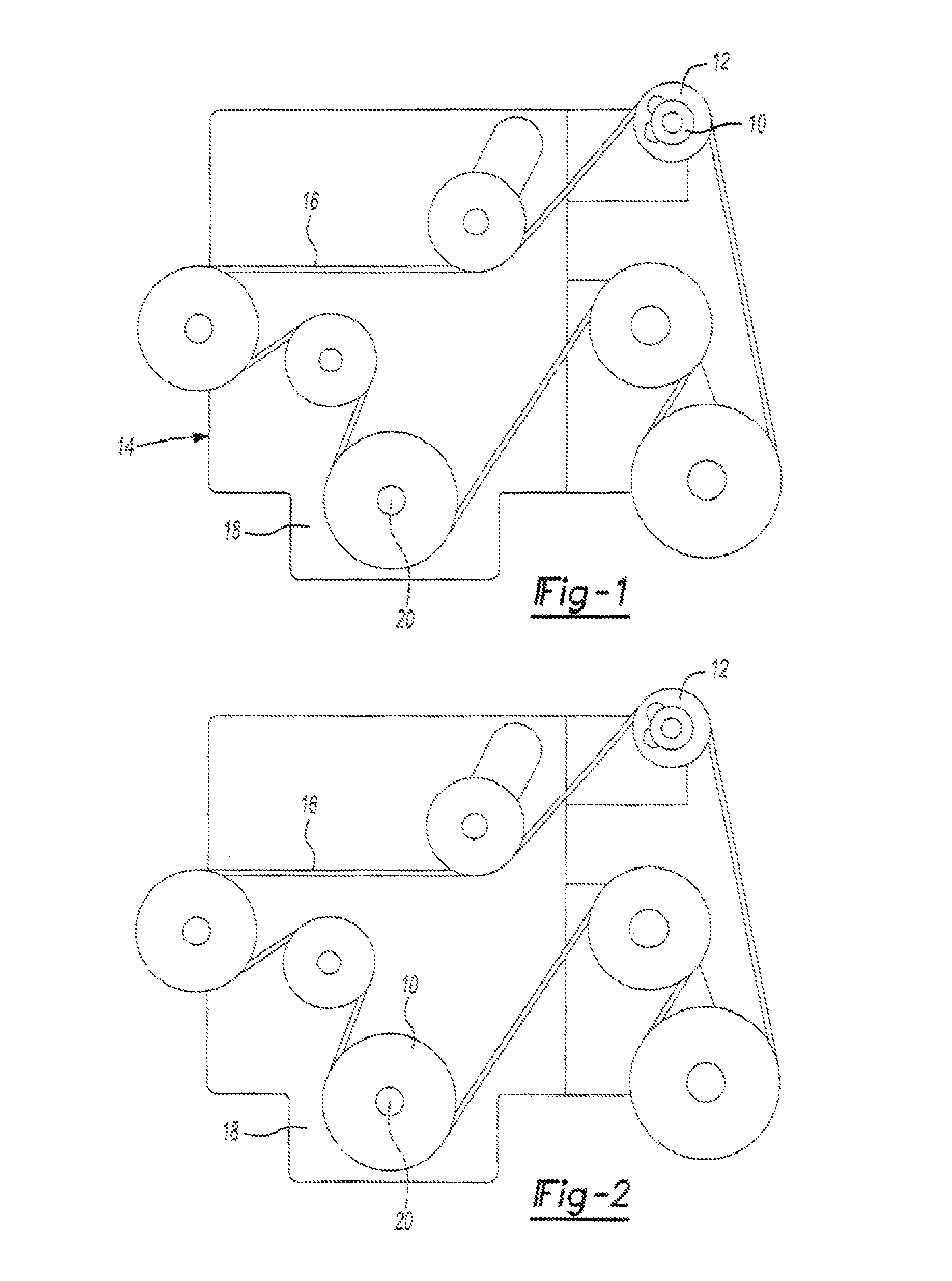
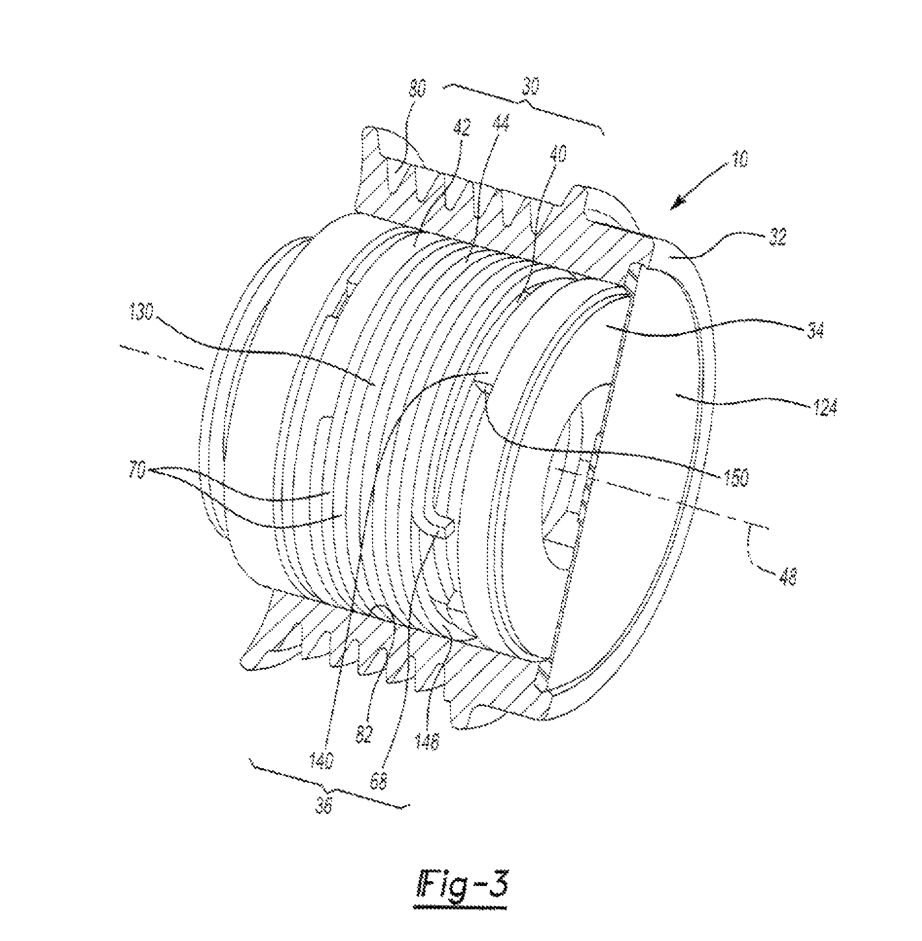
[0022]With reference to FIG. 1 of the drawings, an over-running decoupler constructed in accordance with the teachings of the present disclosure is generally indicated by reference numeral 10. The particular over-running decoupler 10 illustrated is particularly suited for use with a driven device 12, such as an alternator or a supercharger, in a drive system 14 that employs an endless power transmitting element 16, such as a belt or a chain, from a source of rotary power 18, such as an engine or a transmission. Those of skill in the art will appreciate that the over-running decoupler 10 could be configured for use in another type of drive system (e.g., a drive system employing gears) and / or that the over-running decoupler 10 could be employed to transmit rotary power from a drive shaft 20 into the drive system as shown in FIG. 2. Accordingly, it will be appreciated that the teachings of the present disclosure have application in a crankshaft decoupler, similar to those which are dis...


PUM

PropertyMeasurementUnit
rotary poweraaaaaaaaaa
torqueaaaaaaaaaa
peak drive torqueaaaaaaaaaa

Abstract

A method for producing an over-running decoupler that is configured to transmit rotary power between a rotary member and a hub. The over-running decoupler includes a one-way clutch having a clutch spring, a carrier that is coupled to the clutch spring and at least one spring that resiliently couples the carrier to the hub. The method includes: establishing a desired fatigue life of the at least one spring; establishing a design deflection of the at least one spring during resonance, wherein deflection of the at least one spring at the design deflection during resonance does not reduce a fatigue life of the at least one spring below the desired fatigue life; and preventing resonance in the over-running decoupler by controlling a maximum deflection of the at least one spring such that the maximum deflection is less than or equal to the design deflection.

Description

CROSS-REFERENCE TO RELATED APPLICATIONS[0001]This application claims the benefit of U.S. Provisional Patent Application No. 61 / 108,600 filed Oct. 27, 2008, the disclosure of which is hereby incorporated by reference as if fully set forth in detail herein.INTRODUCTION[0002]The present disclosure generally relates to drive systems in which rotary power is transmitted between a source of rotary power and one or more driven components and an over-running decoupler is employed to dampen fluctuations in the torsional load transmitted from the source of rotary power to the driven component, as well as to permit one or more of the driven components to be decoupled from and re-coupled to the source of rotary power to reduce or eliminate torsional loads occurring as a result of deceleration of the source of rotary power relative to the driven component. More particularly, the present disclosure relate to a method for inhibiting a resonant condition in an over-running decoupler.[0003]It is kno...

Claims


Application Information

Patent Timeline
Patent Type & Authority Patents(United States)
IPC IPC(8): F16D7/02F16H9/00F16H55/36F16D3/00F16H61/00F16H55/14F16H59/00F16D41/20F16H63/00
CPCF16D7/022F16D41/206Y10T29/49
Inventor ANTCHAK, JOHN R.XU, JUN
Owner LITENS AUTOMOTIVE INC
Why Eureka
Try Eureka