
Coded articles and systems and methods of identification of the same

a technology of coded articles and codes, applied in the field of coded articles and systems and methods of identification of the same, can solve the problems of inability to detect individual marks with the naked eye, inability or near inability to locate, and inability to locate with an unaided ey

Active Publication Date: 2014-11-25
SHAFFER WAYNE +1
View PDF14 Cites 7 Cited by
  • Summary
  • Abstract
  • Description
  • Claims
  • Application Information

AI Technical Summary

Benefits of technology

The present invention is about a system and method for identifying articles using small codes that can be created and read using a laser. These codes are smaller than traditional barcodes and can be difficult to see with the naked eye. The codes are created by using a laser to make small marks on the surface of the article. The marks are too small to be easily identified by a person without a special reader. The system and method can be used for anti-counterfeiting efforts and to track and locate products. The codes can be included on the internal or external surface of the article and can contain a lot of information about the article.

Problems solved by technology

The small scale size of the code which is created by utilizing a laser to mark the surface of an article is so small that the individual markings cannot be discerned by the naked eye.
In further examples the patch is so small and occupies a surface area that is so small compared to the surface area of the article on which it is positioned that without prior knowledge of the general positioning of the patch on the article or without location landmarks on the article to assist in locating the patch, its discovery or location would be impossible or nearly impossible.
Even if a person had knowledge that an article was marked with such a patch, its location would be impossible or nearly impossible for the person to locate with an unaided eye.
Heretofore such small size markings or apertures were not made for use in barcode identification technology, perhaps in part because existing systems were sufficient for the barcode purposes of the times, such small scale codes were simply not needed or recognized as needed, there was no effective or viable reader capable of reading such small scale markings to use as an efficient identifier, the technology was not developed to create such small markings that could also be accurately read, there was no or little appreciation of the need or capability to establish such small scale system, or for other reasons.

Method used


Image

  • Coded articles and systems and methods of identification of the same
  • Coded articles and systems and methods of identification of the same
  • Coded articles and systems and methods of identification of the same

Examples


Embodiment Construction

[0039]The following detailed description is not to be taken in a limiting sense, but is made merely for the purpose of illustrating the general principles of the invention, since the scope of the invention is best defined by the appended claims.

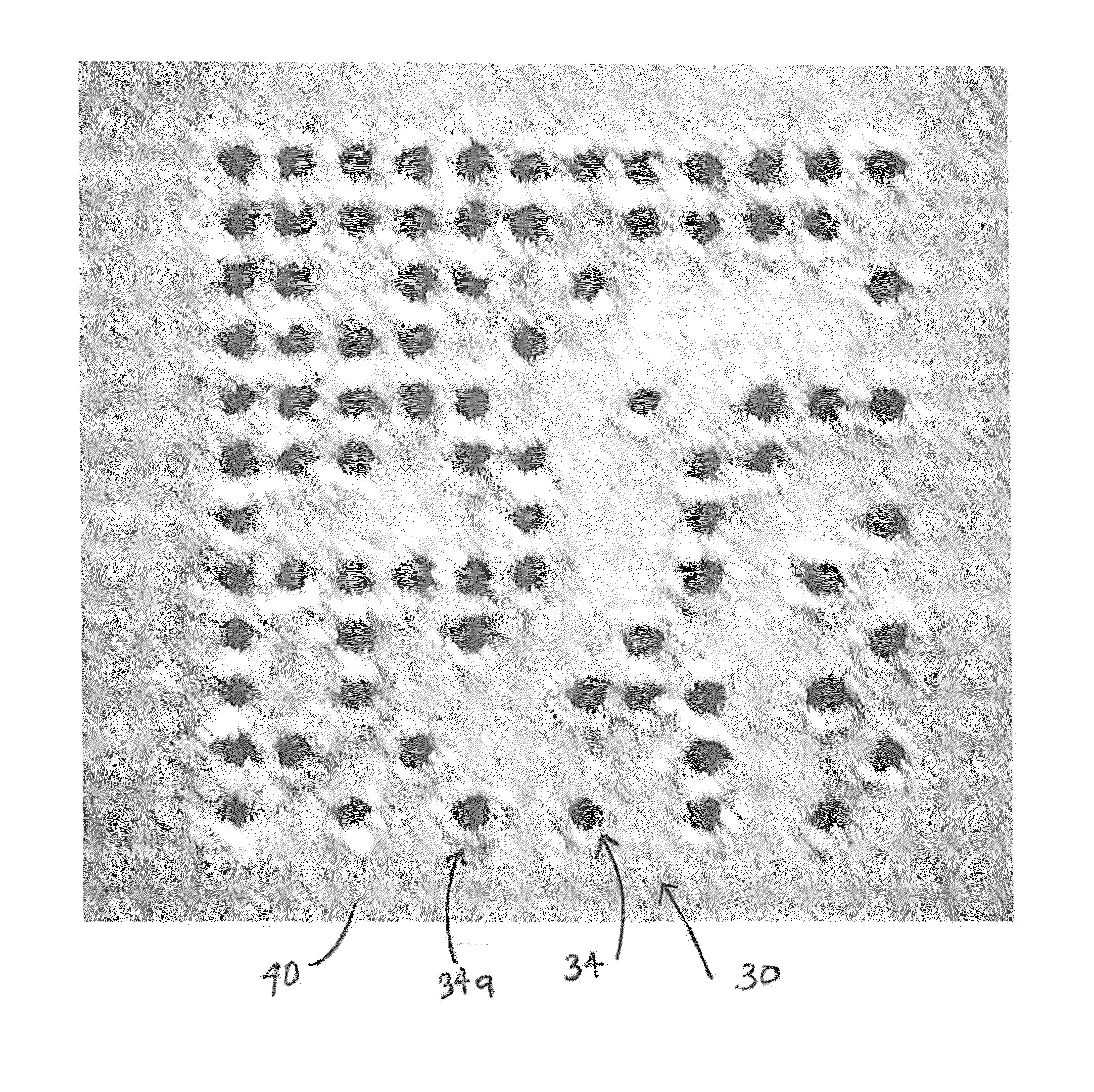
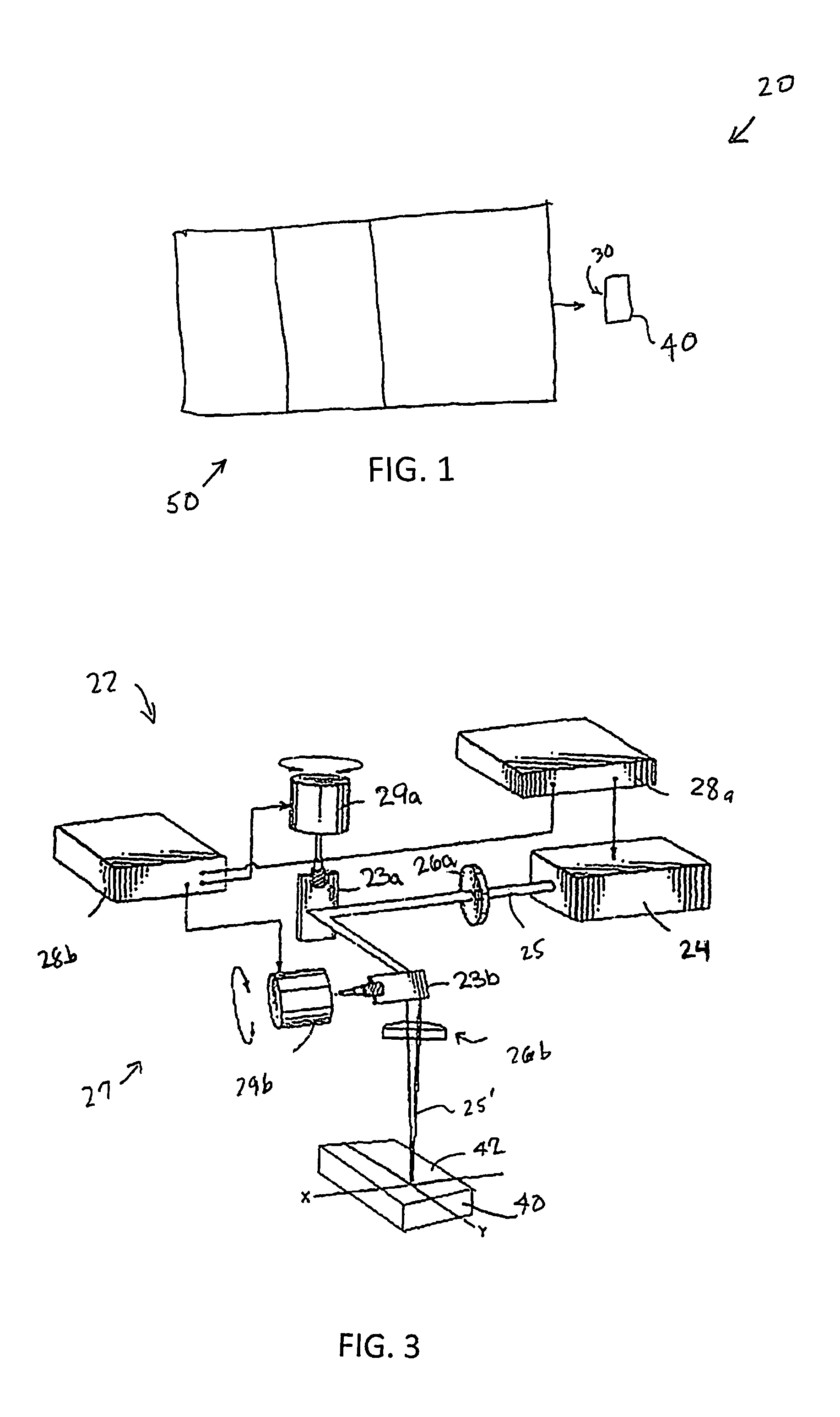
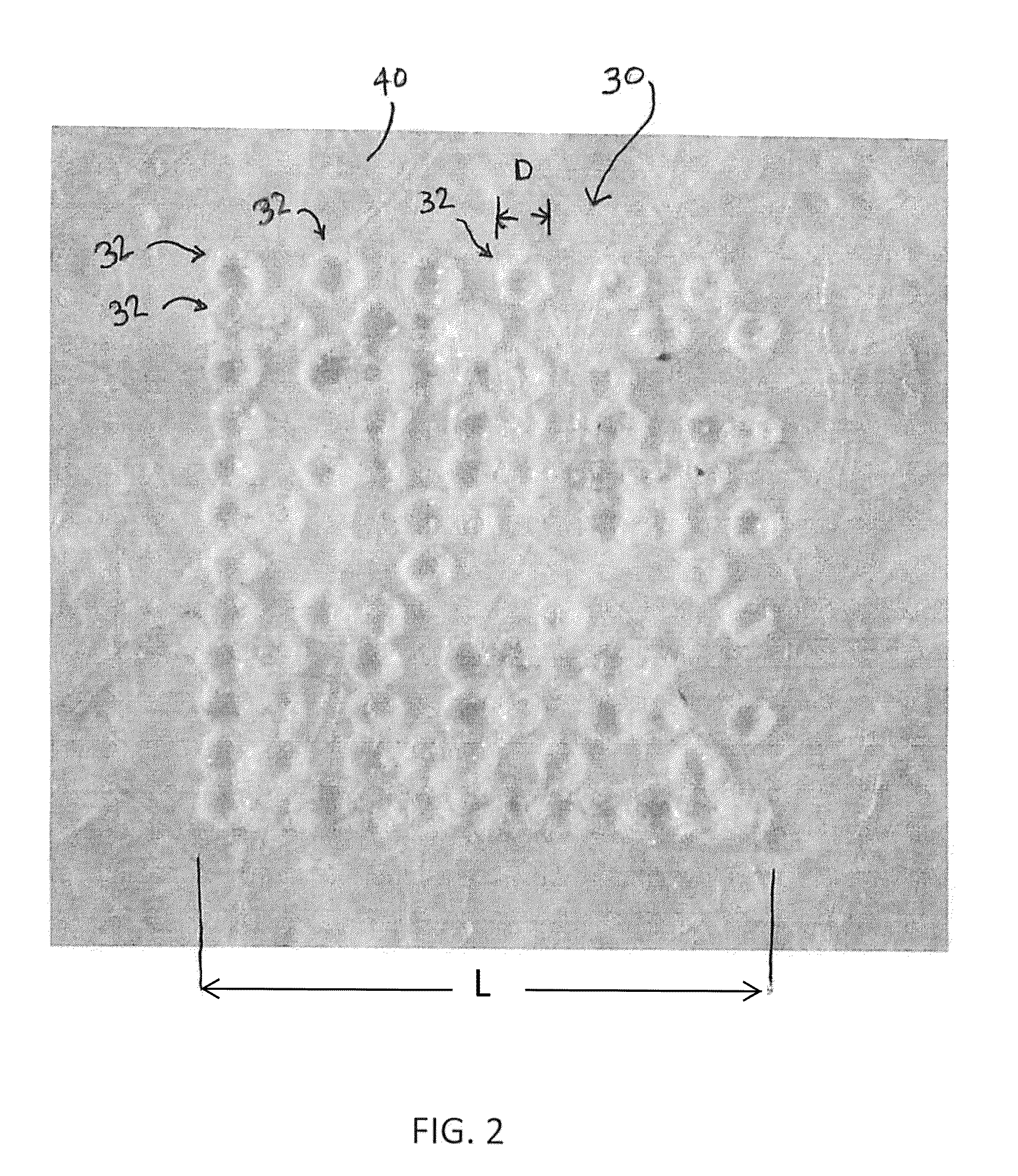
[0040]According to one aspect of the invention generally shown in FIG. 1, an identification system 20 includes a code 30 located on an article 40. Code 30 is read by a reader 50. Code 30 is created by using a laser system 22. Code 30 is a small-sized code that includes a plurality of very tiny holes or very tiny markings that are placed on a surface of article 40. The markings (or holes) are arranged in a pattern that may be read by reader 50. The pattern may be in the form of a barcode. Barcodes may take on many forms. For example, a barcode may be any one or combination of a linear bar code, a stacked bar code, a 2D code, a uniform product code, a micro PDF code, a Smart code, an RSS limited code, and RSS limited composite code, an RSS stac...


PUM


Abstract

A laser scanning system with sufficient power to drill very small holes or marks in materials. The holes or marks are so small that they cannot be seen with the human eye. These holes and marks can be arranged in an ID matrix barcode or other barcode that can be detected with a specially designed barcode reader.

Description

RELATED APPLICATIONS[0001]This application claims the benefit and priority of Provisional Patent Application Ser. No. 61 / 621,174, filed on Apr. 6, 2012, for a Laser & galvanometer scanner to produce a “Micro Barcode” and a reader to decipher the micro-barcode for Anti-counterfeiting purposes, under 35 U.S.C. 119(e), incorporated herein by reference.BACKGROUND OF THE INVENTION[0002]1. Field of the Invention[0003]This invention relates to articles bearing small-sized code markings or apertures in the form of machine-readable barcode images and related systems and methods.[0004]2. Background Information[0005]Barcodes have been used for anti-counterfeiting through data checking and computer based authenticity correlation. Barcodes have also been used in pill identification and identification of other articles. Reference has been made to use of lasers in conjunction with barcode technology. Some examples of articles or systems that utilize laser and / or barcode technology include those di...

Claims


Application Information

Patent Timeline
Patent Type & Authority Patents(United States)
IPC IPC(8): G07D7/12G06K19/06G06K7/015G06K7/14G07D7/00G06K7/10G07D7/20G06K19/00
CPCG07D7/2033G06K7/1447G06K19/06178G07D7/0046G06K7/015G07D7/121G07D7/00G07D7/0043G07D7/005
Inventor SHAFFER, WAYNEKIDO, HIDEO
Owner SHAFFER WAYNE
Learn More