Surgical prostheses

a prosthesis and implant technology, applied in the field of surgical prosthesis, can solve the problems of inexperienced surgeons, restricted hip movement, difficulty in positioning the cup, etc., and achieve the effect of increasing the porosity or surface area of the substrate and promoting osseointegration

Active Publication Date: 2014-11-25
DUPUY INT LTD
View PDF73 Cites 2 Cited by
  • Summary
  • Abstract
  • Description
  • Claims
  • Application Information

AI Technical Summary

Benefits of technology

[0013]An advantage of the first aspect of the present invention is that the alignment mark assists a surgeon in aligning the prosthesis relative to local bone landmarks. For instance, for embodiments of the present invention relating to acetabular cups, the alignment mark may indicate a correct alignment of the cup relative to the acetabular cavity. More specifically, the alignment mark may advantageously identify to the surgeon the correct proportion of the cup to protrude from the bone cavity. This reduces the risk of a cup incorrectly being inserted flush with the acetabular rim or the inclination angle being set incorrectly due to th

Problems solved by technology

However, inexperienced surgeons may mistakenly believe that the cup is intended to be seated and secured in position flush with the acetabulum rim in order to replicate the cups natural orientation.
This is incorrect and can restrict the movement of the hip.
A second problem with conventional acetabular cup placement results from difficulty in positioning the cup owing to the surgeons viewing angle.
This compound angle

Method used


Image

  • Surgical prostheses
  • Surgical prostheses

Examples


Embodiment Construction

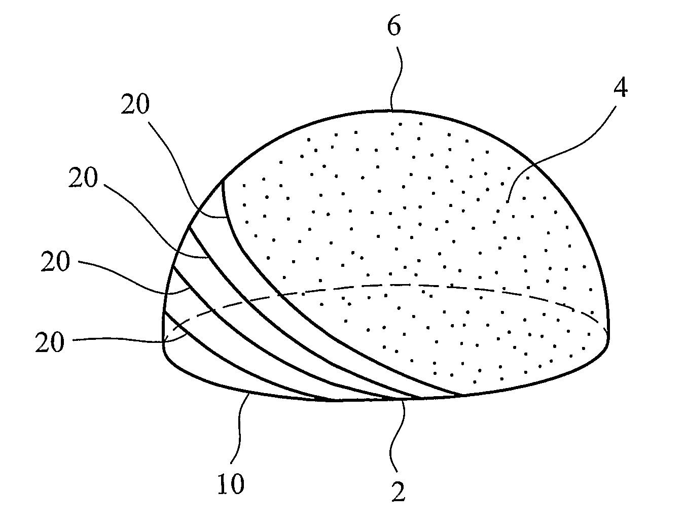
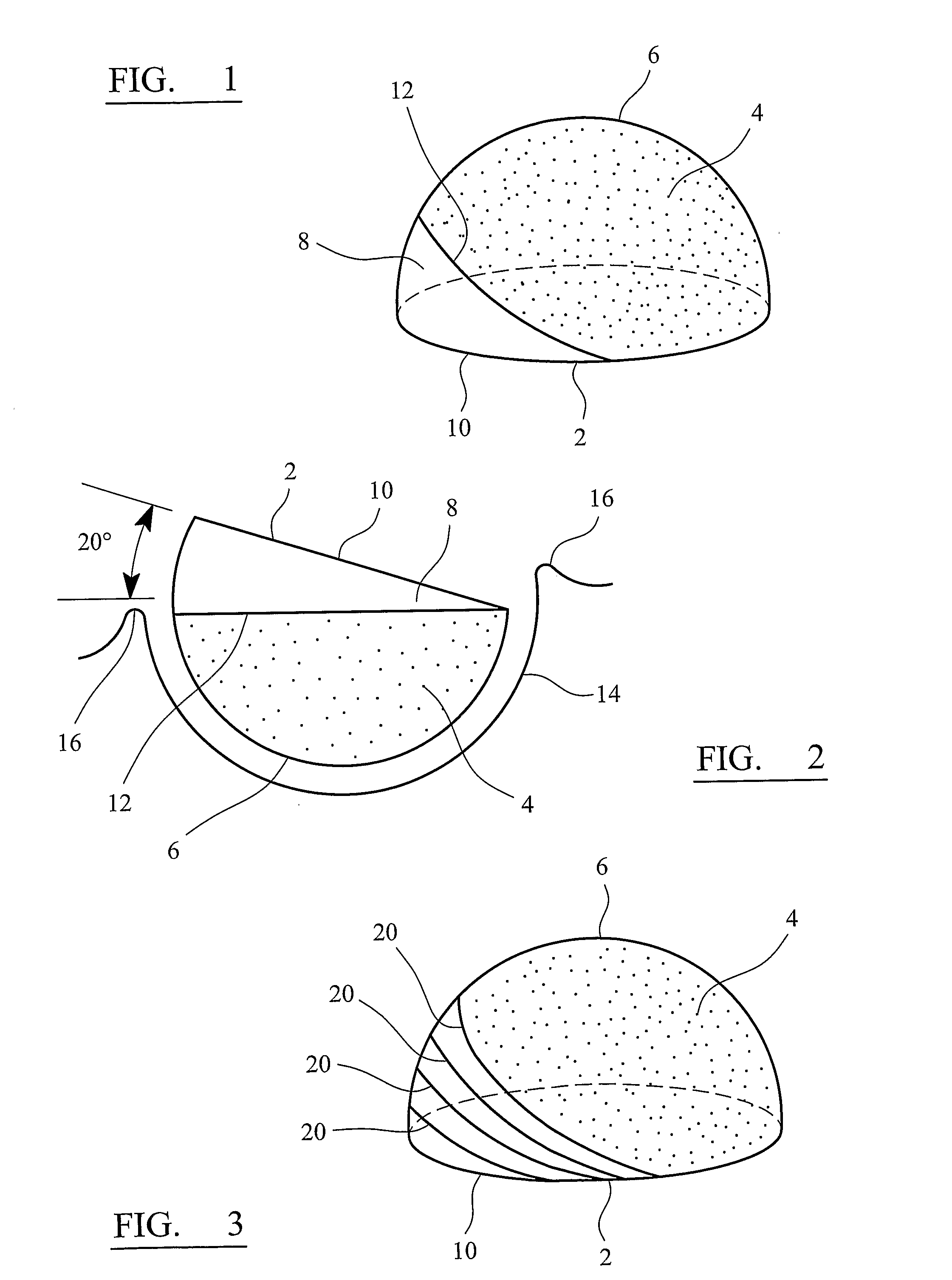
[0028]Referring first to FIG. 1, this illustrates an acetabular cup comprising a hollow, generally hemispherical metal substrate 2 and a coating 4 over a portion of the convex surface 6, which when implanted is at least partially in contact with the bone. The coating 4 is intended to promote osseointegration and may be a porous coating such as Porocoat or a bioactive coating such as hydroxyapatite or any other similar coating material applicable to a surface of a prosthesis. The cup may have additional bone fixation means, for instance a screw hole (not shown) generally positioned at the pole of the hemisphere. The coating 4 extends over the majority of the convex surface 6, but is interrupted by an uncoated portion 8 which extends from one edge of the cup rim 10. The uncoated portion 8 is separated from the coating along a dividing line 12 which extends along an arc across the convex surface 6. The arc may begin and end at discrete points about the rim 10, or may extend to and from...


PUM

PropertyMeasurementUnit
Angleaaaaaaaaaa
Shapeaaaaaaaaaa
Areaaaaaaaaaaa

Abstract

A prosthesis arranged to be coupled to a bone. The prosthesis comprises a substrate (2) having a surface (6). The surface (6) of the substrate (2) has a first area and a second area, the first area being treated such that osteointegration is promoted more than in the second area. The interface (12) between the first and second areas forms an alignment mark to assist alignment of the prosthesis relative to a bone. The prosthesis is arranged to be at least partially inserted into a bone cavity such that the position of the alignment mark relative to the bone cavity is indicative of the angle of insertion of the prosthesis or the alignment mark provides a position reference for determining the implanted position of the prosthesis in the cavity. A method of manufacturing the prosthesis and a method of implanting the prosthesis are also provided.

Description

CROSS REFERENCE TO RELATED APPLICATION[0001]This application is a National Stage 35 U.S.C. 371 of International Patent Application PCT / GB2010 / 000718 filed Apr. 9, 2010.BACKGROUND OF THE INVENTION[0002]The present invention relates to surgical prostheses. The present invention is particular suited to a rotationally symmetrical surgical prosthesis such as an acetabular cup.[0003]It is well known to repair bone joints damaged through disease or injury by implanting prosthetic components to replace part or all of the natural bone joint. For example, surgical reconstruction of a hip joint may require a femoral prosthetic component implanted at the end of the femur to replace the natural femoral head with a prosthetic bearing head and a prosthetic acetabular cup implanted within a reamed acetabular cavity or the natural acetabulum to receive the prosthetic bearing head.[0004]There are a range of different fixation techniques known for securing prostheses to the surface of bones, or within...

Claims


Application Information

Patent Timeline
IPC IPC(8): A61F2/30A61F2/34A61F2/32
CPCA61F2/30A61F2250/0097A61F2002/30617A61F2/3094A61F2002/30029A61F2/34A61F2310/00796A61F2002/3092A61F2002/3093A61F2002/30028
Inventor BIRKBECK, ALECCOLLINS, RYAN
Owner DUPUY INT LTD
Why Eureka
Try Eureka