Method of automatic target angle tracking by monopulse radar under conditions of interference distorting location characteristic

a monopulse radar and target angle technology, applied in the field of radiolocation sphere, can solve problems such as loss of automatic target angle tracking, and achieve the effect of improving guidance accuracy

Inactive Publication Date: 2014-11-25
MARKIN EVGENY
View PDF1 Cites 7 Cited by
  • Summary
  • Abstract
  • Description
  • Claims
  • Application Information

AI Technical Summary

Benefits of technology

[0001]The invention relates generally to radiolocation sphere, and particularly to monopulse direction finding systems. It can be used to increase guidance accuracy, for example, of unmanned aerial vehicles to radar targets such as: radio beacons; aerial vehicles reflecting the radio signal that illuminates them; aerial vehicles and ground-based devices radiating radio signals and jamming signals.
[0005]A method of target angle tracking is known, that is the closest to the claimed one herein, which is based on the use of polarization filtering of electromagnetic waves coming from the target in the sum-and-difference monopulse radio direction-finder (See [1], p. 69-71, p. 168-169). In this case polarization filtering is performed with the help of the polarization array mounted in the monopulse antenna mouth that allows to weaken an adverse effect of signals on cross polarization on the target direction finding accuracy.
[0010]Thus, the aim and the main technical result of the present invention is to ensure stability of automatic angle tracking on target.
[0018]The essence of the invention consists in the assurance of reliability and stability and in the enhancement of guidance accuracy of automatic target angle tracking due to elimination of automatic tracking losses and great errors arising during the influence of the signals of orthogonal polarization or polarization close to it.

Problems solved by technology

In this case at the output of phase detector 9 abruptly increases the angle tracking error which leads to the loss of automatic angle tracking on target.

Method used


Image

  • Method of automatic target angle tracking by monopulse radar under conditions of interference distorting location characteristic
  • Method of automatic target angle tracking by monopulse radar under conditions of interference distorting location characteristic
  • Method of automatic target angle tracking by monopulse radar under conditions of interference distorting location characteristic

Examples


example 1

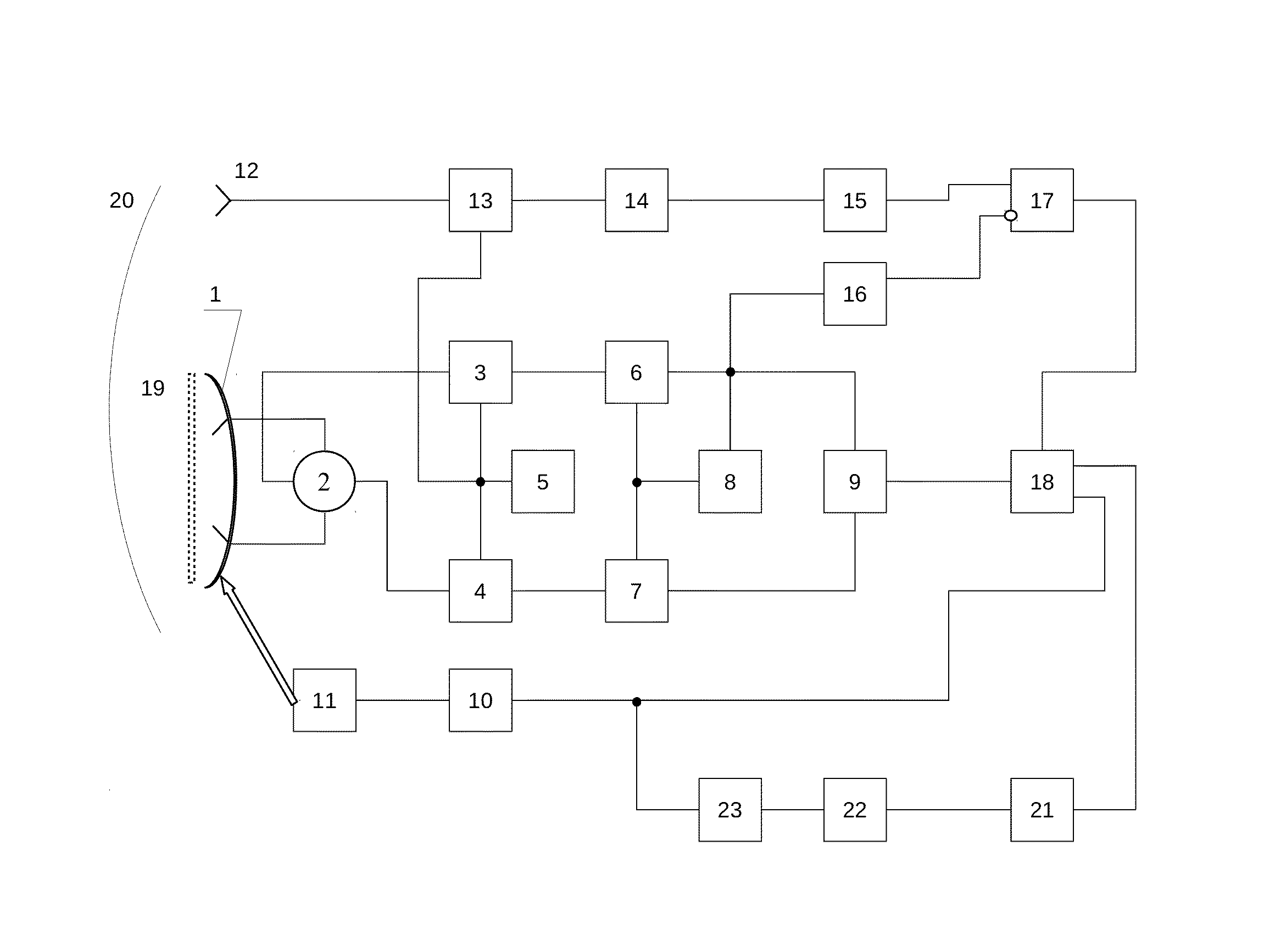
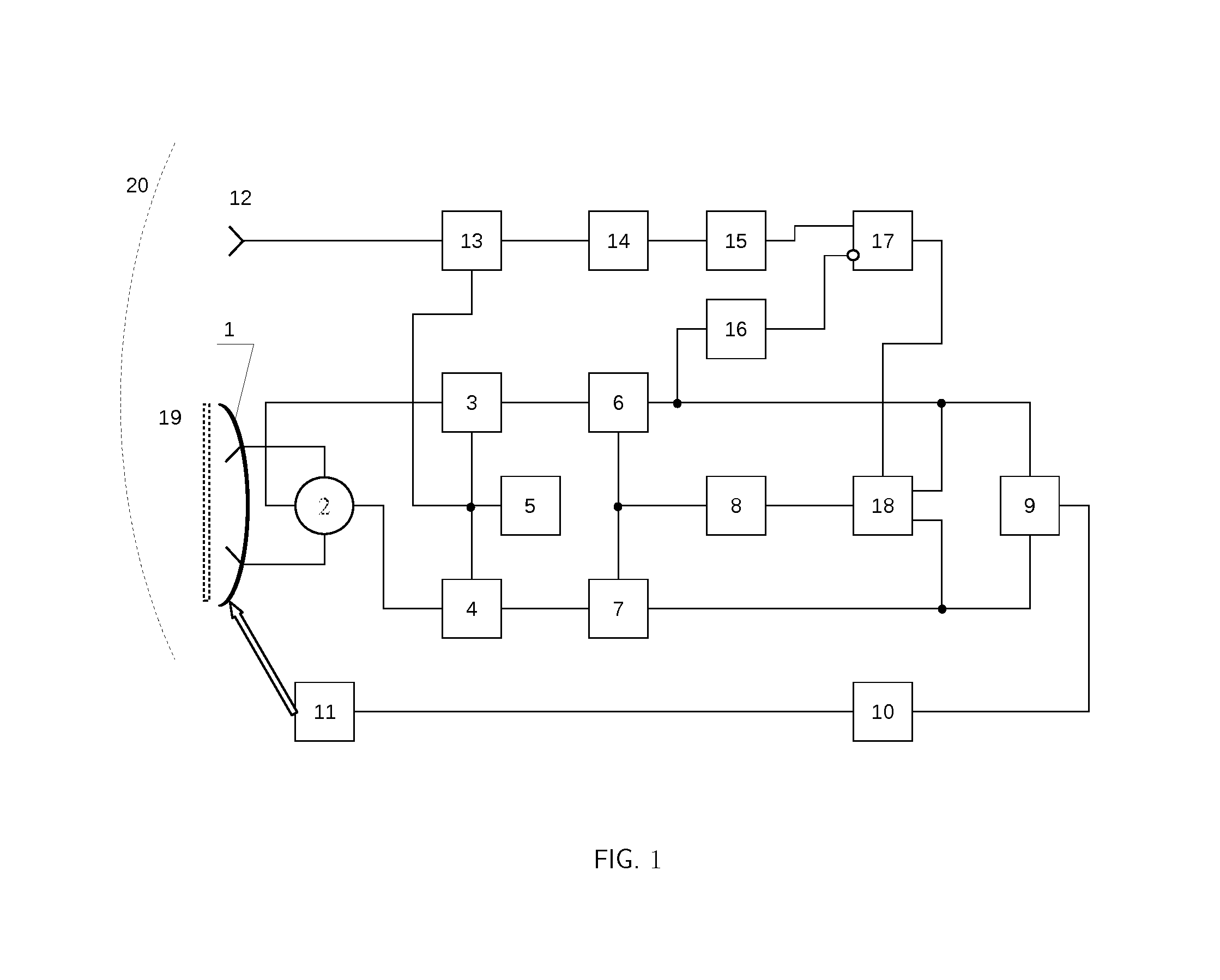
[0073]The radio direction-finder (FIG. 1) comprises monopulse antenna 1 (for example, a paraboloid of revolution with two-mode feed) in the mouth of which is mounted a polarization filter 19. The working polarization for antenna 1 is a vertical one. The outputs of antenna 1 are connected to the sum-and-difference device in the form of stripline ring 2, the sum output of which is connected to mixer 3 and the difference output—to mixer 4. Mixers 3 and 4 are also connected to heterodyne 5 which is also connected to mixer 13. The signal input of mixer 13 is connected to horn antenna 12 having the horizontal working polarization (orthogonal relative to the working polarization of monopulse antenna 1), which is mounted on the edge of antenna 1. The output of the mixer 13 is connected to the input of the intermediate-frequency amplifier of the additional channel 14. The outputs of mixers 3 and 4 are connected respectively to the inputs of intermediate-frequency amplifiers 6 and 7, the outp...

example 2

[0113]The radio direction-finder (FIG. 12) includes monopulse antenna 1 (for example, a paraboloid of revolution with two-mode feed) in the mouth of which polarization filter 19 is mounted. The working polarization for antenna 1 is a vertical one. The outputs of antenna 1 are connected to the sum-and-difference device in the form of stripline ring 2, the sum output of which is connected to mixer 3 and the difference output—to mixer 4. Mixers 3 and 4 are also connected to heterodyne 5 which is also connected to mixer 13. The signal input of mixer 13 is connected to the output of horn antenna 12 having the horizontal working polarization (orthogonal relative to the working polarization of monopulse antenna 1), which is mounted on the edge of antenna 1. The output of the mixer 13 is connected to the input of the intermediate-frequency amplifier of the additional channel 14. The outputs of mixers 3 and 4 are connected respectively to the inputs of intermediate-frequency amplifiers 6 and...


PUM


Abstract

Method of automatic target angle tracking by sum-and-difference monopulse radar covers radiolocation sphere and specifically monopulse direction finding systems. It can be used in order to increase guidance accuracy, for example, for anti aircraft missiles and of unmanned aerial vehicles to radar targets such as: radio beacons; aerial vehicles reflecting the radio signal that illuminates them; aerial vehicles and ground-based devices radiating radio signals and jamming signals. The aim of the method consists in the assurance of reliability and stability and in the enhancement of guidance accuracy of automatic target angle tracking due to elimination of automatic tracking losses and great errors arising during the influence of the signals of orthogonal polarization or polarization close to it.The proposed method provides full protection from polarization jamming for all types of monopulse radars.

Description

[0001]The invention relates generally to radiolocation sphere, and particularly to monopulse direction finding systems. It can be used to increase guidance accuracy, for example, of unmanned aerial vehicles to radar targets such as: radio beacons; aerial vehicles reflecting the radio signal that illuminates them; aerial vehicles and ground-based devices radiating radio signals and jamming signals.[0002]It is commonly known that the presence of antenna cross-polarization radiation leads to reduction of direction finding accuracy; it can result in the complete failing of the monopulse direction finding system, i.e. automatic tracking loss [1] (Chapters 6, 8), [2]. The said phenomenon occurs during direction finding of the targets with marked depolarization effect which is the majority of real aerodynamic targets possess. But this problem is most important when so-called polarization interference is used as electronic countermeasures means [1] (paragraph 8.5.2), [2], [3].[0003]A method...

Claims


Application Information

Patent Timeline
Patent Type & Authority Patents(United States)
IPC IPC(8): G01S3/08H01Q25/02G01S3/32G01S13/00
CPCH01Q25/02G01S3/08G01S3/325
Inventor MARKIN, EVGENY
Owner MARKIN EVGENY
Why Eureka
Try Eureka