
Systems and methods for accelerating charged particle beams

a technology of charged particles and beams, applied in the field of methods and systems for accelerating charged particle beams, can solve the problems of large voltages for operation and higher manufacturing costs, and achieve the effect of increasing distan

Inactive Publication Date: 2014-11-25
SCI RES LAB
View PDF19 Cites 3 Cited by
  • Summary
  • Abstract
  • Description
  • Claims
  • Application Information

AI Technical Summary

Benefits of technology

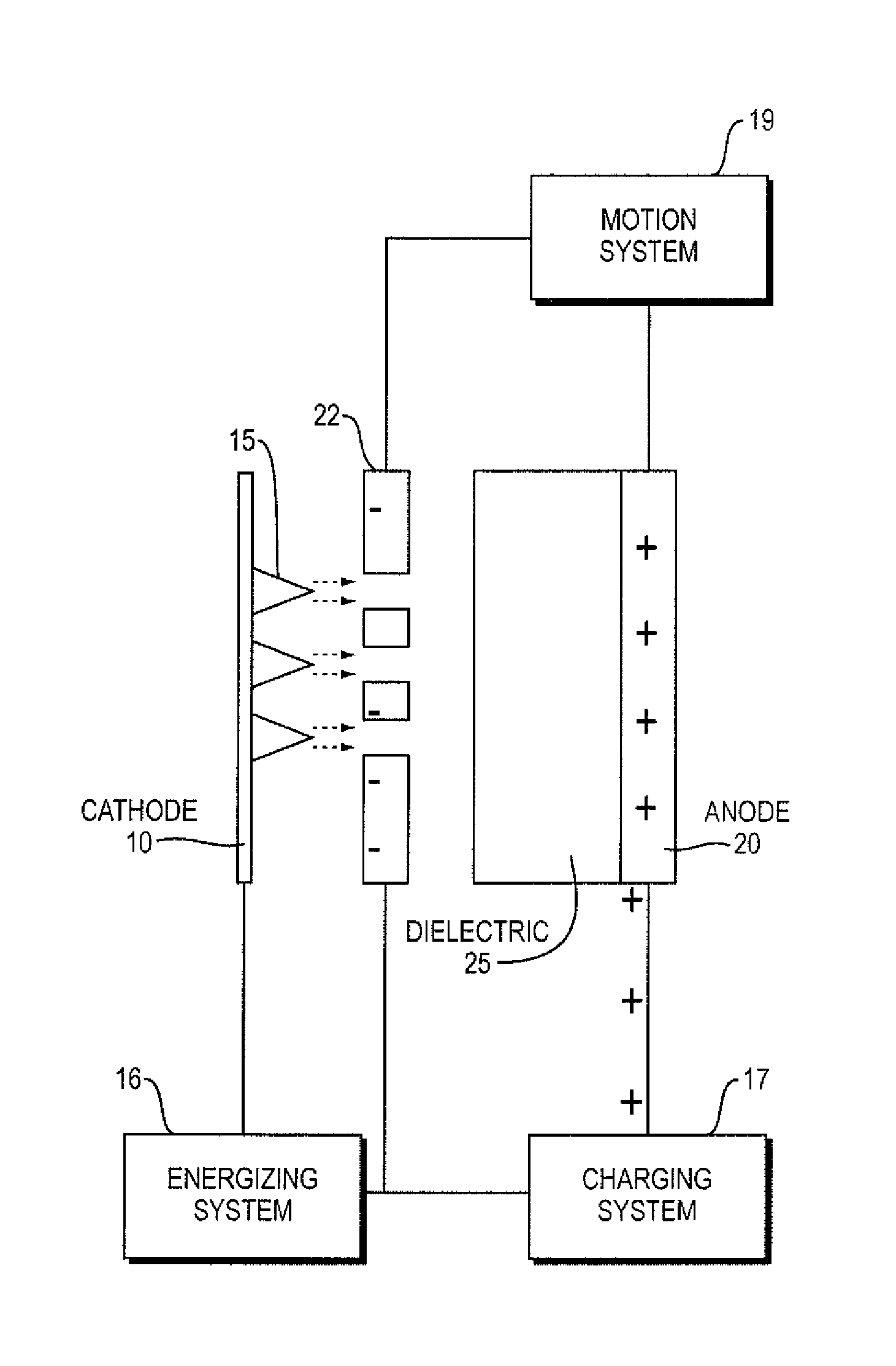
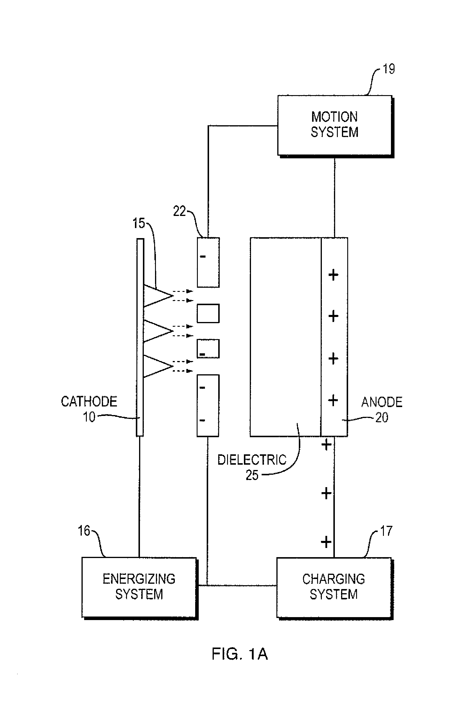
The patent describes a device that can create a charged particle beam quickly. The device has a charged structure that creates a capacitive structure with a grid, and uses a charging component to charge that structure. A motion subsystem then moves the charged structure to cause the charged particles to be emitted. The technical effect of this method is that it allows for a faster and more efficient way to create a charged particle beam.

Problems solved by technology

Carbon nanotubes have a lower threshold electric field for emission but still require large voltages for operation and could require a higher expense in manufacturing.

Method used


Image

  • Systems and methods for accelerating charged particle beams
  • Systems and methods for accelerating charged particle beams
  • Systems and methods for accelerating charged particle beams

Examples


Embodiment Construction

[0020]The following detailed description is of the best currently contemplated modes of carrying out these teachings. The description is not to be taken in a limiting sense, but is made merely for the purpose of illustrating the general principles of these teachings, since the scope of these teachings is best defined by the appended claims. Although the teachings have been described with respect to various embodiments, it should be realized these teachings are also capable of a wide variety of further and other embodiments within the spirit and scope of the appended claims.

[0021]As used herein, the singular forms “a,”“an,” and “the” include the plural reference unless the context clearly dictates otherwise.

[0022]Except where otherwise indicated, all numbers expressing quantities of ingredients, reaction conditions, and so forth used in the specification and claims are to be understood as being modified in all instances by the term “about.”

[0023]Embodiments of systems and methods for...


PUM


Abstract

Embodiments of micro-x-ray sources and methods for obtaining a micro-x-ray source are disclosed.

Description

CROSS REFERENCE TO RELATED APPLICATIONS[0001]This application claims priority to U.S. Provisional Application Ser. No. 61 / 442,460, filed Feb. 14, 2011, entitled SYSTEMS AND METHODS FOR CONVERTING / STORING ENERGY WITH APPLICATION TO GENERATING MICRO X-RAY SOURCES, which is incorporated by reference herein in its entirety and for all purposes.BACKGROUND[0002]This invention relates generally to methods and systems for accelerating charged particle beams and to applications of those methods and systems. Among the applications are application to x-ray sources, and, more particularly, to micro-x-ray sources.[0003]The storing of electrical energy has seen application in pulsed power systems and in other power systems. In one well-known example, in work initiated by J. C. Martin of AERE (UK), energy storage in capacitors has been used for the generation of electron beams. While such initial work was aimed at very large systems, there is a need for technology that relates to the storing / conve...

Claims


Application Information

Patent Timeline
IPC IPC(8): H01J29/46H01J35/04H01J27/02
CPCH01J35/04H01J2235/062H01J2235/068H01J2235/10H05G1/04
Inventor JACOB, JONAH, H.
Owner SCI RES LAB
Learn More