Exhaust gas recirculation control device of internal combustion engine

a technology of exhaust gas recirculation and control device, which is applied in the direction of electrical control, process and machine control, instruments, etc., can solve the problems of complex control flow process, achieve the effect of preventing excessive opening of egr control valve, improving control valve reliability, and tracking performan

Active Publication Date: 2014-11-25
MITSUBISHI HEAVY IND ENGINE & TURBOCHARGER LTD
View PDF14 Cites 0 Cited by
  • Summary
  • Abstract
  • Description
  • Claims
  • Application Information

AI Technical Summary

Benefits of technology

[0068]According to the present invention, the overshoot of the EGR control valve opening relative to the target valve opening can be prevented; the smoke generation due to the excessive opening of the EGR control valve can be prevented; and the tracking performance as well as the reliability of the EGR control valve can be enhanced.
[0069]Further, the feedback control command signal and the feed-forward control command signal are computed in response to the operation conditions of the internal combustion engine. Thus, by intentionally changing and setting the feedback control target signal for computing the feedback control command signal, for instance, by setting the data of a feedback control target map at a data which is intentionally changed from a desirable data in a case of a low load operation range, the selection unit can be set so as to select only the feed-forward control command signal in the low load operation range. In this way, with simple control logic, the change-over between the control only by the feed-forward control command signal and the control by the aggregation of the feed-forward control command signal and the feedback control command signal can be performed.

Problems solved by technology

Thus, there arises a problem that the processes of the control flow to be executed become complicated.

Method used


Image

  • Exhaust gas recirculation control device of internal combustion engine
  • Exhaust gas recirculation control device of internal combustion engine
  • Exhaust gas recirculation control device of internal combustion engine

Examples


Embodiment Construction

[0085]Hereafter, the present invention will be described in detail with reference to the modes or embodiments shown in the figures. However, the dimensions, materials, shape, the relative placement and so on of a component described in these modes or embodiments shall not be construed as limiting the scope of the invention thereto, unless especially specific mention is made.

(First Mode)

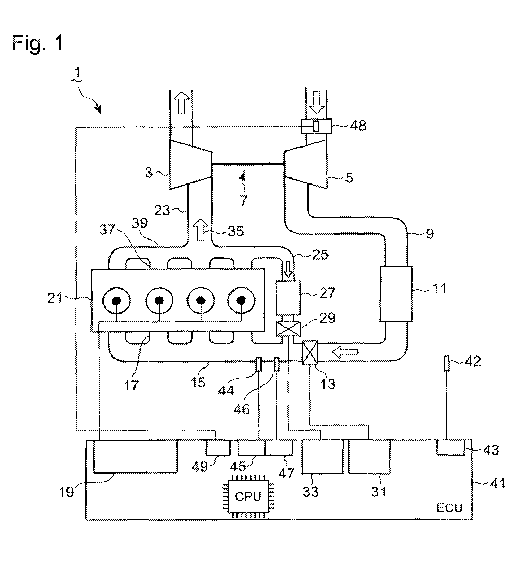
[0086]Based on FIG. 1, an exhaust gas recirculation control device of an internal combustion engine according to a first mode of the present invention is now explained.

[0087]As shown in FIG. 1, a diesel engine (hereafter abbreviated to an engine) is provided with an exhaust turbocharger 7 including, but not limited to, an exhaust turbine 3 and a compressor 5 which is driven by a coaxial shaft common to the turbine 3 and the compressor 5; an intake air delivered from the compressor 5 of the exhaust turbocharger 7 streams through an intake air passage 9 and enters an intercooler 9; after the intake air ...


PUM


Abstract

An exhaust gas recirculation control device is provided with a feedback control unit and a feed-forward control unit, wherein the device is provided with: an adder which adds a feed-forward control command signal to a feedback control command signal; and a maximum selection function-section which compares an added value obtained by the adder with a feed-forward control command signal or a command signal from an EGR valve maximum opening map, and selects the command signal by which the valve opening of the EGR control valve is brought to a closed side, wherein the command signal by which the valve opening of the EGR control valve is brought to an opened side is not outputted.

Description

BACKGROUND OF THE INVENTION[0001]1. Field of the Invention[0002]The present invention relates to an exhaust gas recirculation device of an internal combustion engine.[0003]2. Background of the Invention[0004]As a measure to reduce NOx emission from an internal combustion engine, it has been a conventional practice to provide the internal combustion engine with an EGR (Exhaust Gas Recirculation) device.[0005]Thereby, an EGR gas control valve for controlling the flow rate of an EGR gas is conventionally provided in an EGR gas passage which connects an exhaust gas passage to an intake air passage; the opening of the EGR control valve is controlled by a feedback correction device so that the opening of the EGR control valve follows a target opening that is determined in response to the operation condition of the internal combustion engine.[0006]However, in a transient operation condition, it is not always possible to perform the operation under a pertinent target opening condition. In a...

Claims


Application Information

Patent Timeline
Patent Type & Authority Patents(United States)
IPC IPC(8): F02D41/18F02D41/00F02D41/24F02D41/14F02M25/07F02D41/10
CPCF02D41/005F02M25/0707F02D2041/0017F02D2200/0406F02D2041/1409F02D41/18F02D2200/0614Y02T10/47F02D2200/101F02D41/107F02D41/1458F02D41/1401F02D2041/141F02D2200/0414F02M26/05Y02T10/40F02D21/08
Inventor IDE, KAZUNARIENDO, HIROYUKI
Owner MITSUBISHI HEAVY IND ENGINE & TURBOCHARGER LTD
Why Eureka
Try Eureka