Methods and apparatus for detecting the confinement state of plasma in a plasma processing system

a plasma processing system and confinement state technology, applied in the direction of measuring devices, instruments, electric discharge tubes, etc., can solve the problems of plasma non-uniformity, particle contamination, plasma yield degradation under process and/or damage to the plasma processing system,

Active Publication Date: 2014-12-02
LAM RES CORP
View PDF43 Cites 31 Cited by
  • Summary
  • Abstract
  • Description
  • Claims
  • Application Information

AI Technical Summary

Problems solved by technology

Unconfined plasma can cause particle contamination and plasma non-uniformities, leading to degradation in the yield of the substrate under process and / or damage to the plasma processing system.
While this instrument provides a relatively reliable means of detecting a change in plasma confinement by providing a DC (direct current) measurement of plasma sheath potential, it is a consumable part that must be replaced frequently and can induce plasma non-uniformities at higher RF powers and can result in particle contamination issues.
However, it has been found that monitoring OES signals is an unduly complex and oftentimes unreliable method of detecting plasma unconfinement events.

Method used


Image

  • Methods and apparatus for detecting the confinement state of plasma in a plasma processing system
  • Methods and apparatus for detecting the confinement state of plasma in a plasma processing system
  • Methods and apparatus for detecting the confinement state of plasma in a plasma processing system

Examples


Embodiment Construction

[0010]The present invention will now be described in detail with reference to a few embodiments thereof as illustrated in the accompanying drawings. In the following description, numerous specific details are set forth in order to provide a thorough understanding of the present invention. It will be apparent, however, to one skilled in the art, that the present invention may be practiced without some or all of these specific details. In other instances, well known process steps and / or structures have not been described in detail in order to not unnecessarily obscure the present invention.

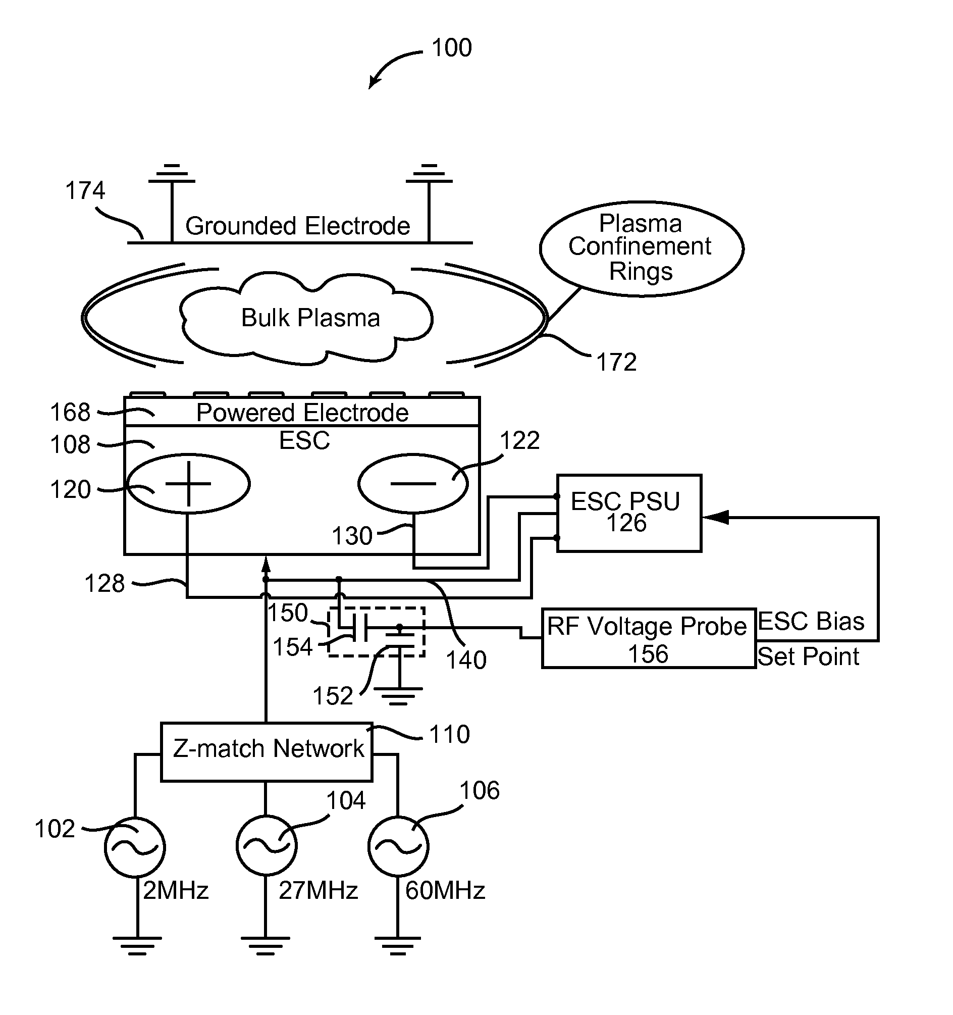
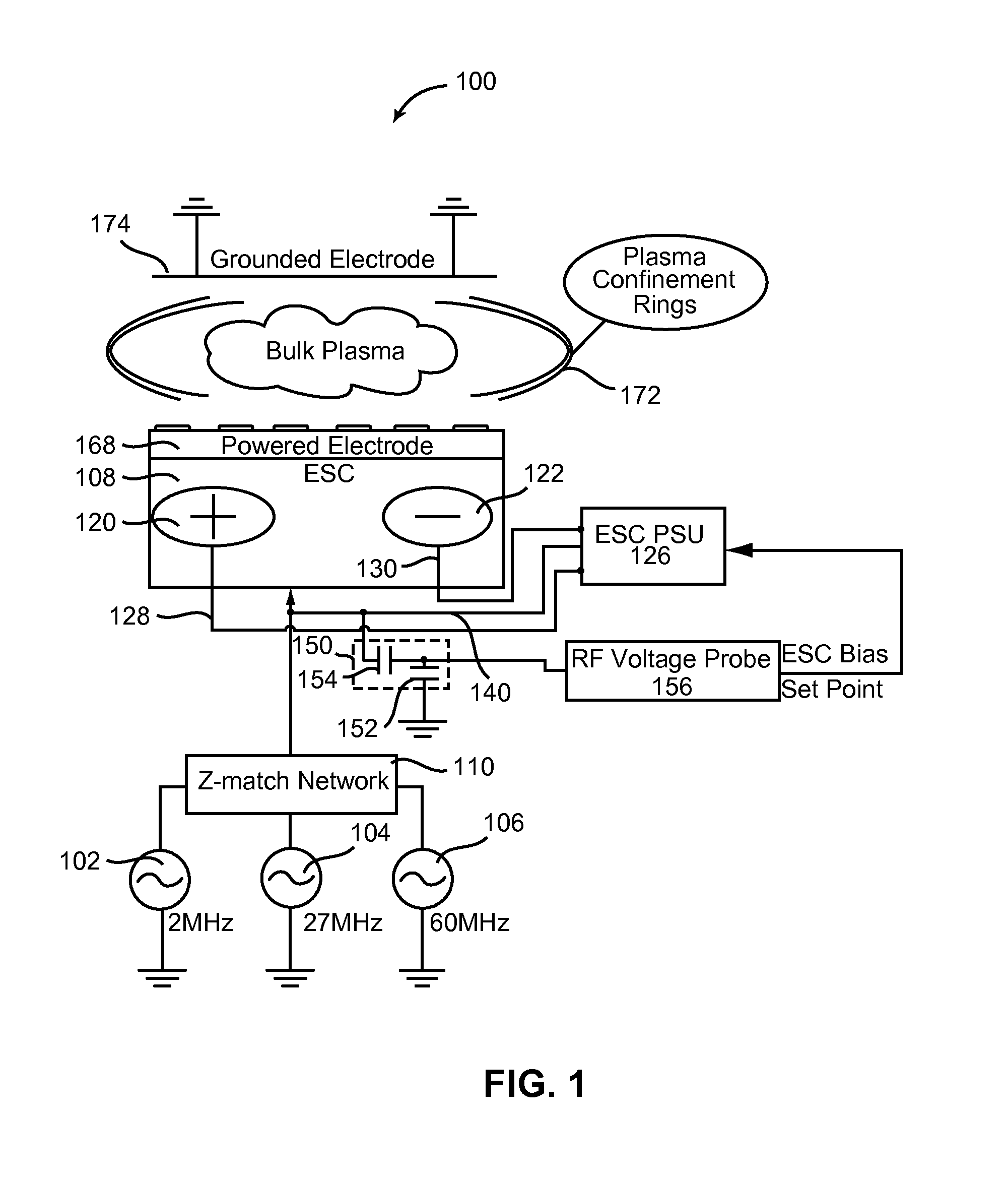
[0011]In one or more embodiments, methods and apparatus for detecting a change in the state of plasma confinement within a capacitively coupled, RF driven plasma processing chamber are disclosed. In one or more embodiments, the plasma unconfinement detection methods employ an analog and / or digital circuit that can actively poll the RF voltage at the powered electrode in the form of an Electrostatic ...


PUM

PropertyMeasurementUnit
RF frequenciesaaaaaaaaaa

Abstract

Methods and systems for detecting a change in the state of plasma confinement within a capacitively coupled RF driven plasma processing chamber are disclosed. In one or more embodiments, the plasma unconfinement detection methods employ an analog or digital circuit that can actively poll the RF voltage at the powered electrode in the form of an Electrostatic Chuck (ESC) as well as the open loop response of the power supply (PSU) responsible for chucking a wafer to ESC. The circuit provides a means detecting both a change in RF voltage delivered to the ESC as well as a change in the open loop response of the PSU. By simultaneously monitoring these electrical signals, the disclosed algorithm can detect when plasma changes from a confined to an unconfined state.

Description

PRIORITY CLAIM[0001]This application claims priority under 35 USC. 119(e) to a commonly-owned provisional patent application entitled “BIAS COMPENSATION APPARATUS AND METHODS THEREFOR”, U.S. application Ser. No. 61 / 303,628, filed on Feb. 10, 2010 by John Valcore, Jr. and a commonly-owned provisional patent application entitled “METHOD AND DEVICE FOR COMPENSATING WAFER BIAS IN A RF DRIVEN PLASMA CHAMBER”, U.S. application Ser. No. 61 / 262,886, filed on Nov. 19, 2009 by John Valcore, Jr., both of which are incorporated herein by reference.BACKGROUND OF THE INVENTION[0002]In the manufacture of semiconductor products, substrates (e.g., semiconductor wafers) are processed by successively depositing, etching, and polishing various layers to create semiconductor devices. Within the semiconductor industry, it is common practice to utilize the benefits of a RF (Radio Frequency) driven plasma to dry etch material from a substrate. During plasma etch processes, it is paramount that the stabilit...

Claims


Application Information

Patent Timeline
Patent Type & Authority Patents(United States)
IPC IPC(8): G01N27/62
CPCG01N27/62H01L21/67253H01L21/6831H01J37/32917
Inventor VALCORE, JR., JOHN C.ROGERS, JAMES
Owner LAM RES CORP
Why Eureka
Try Eureka