Signal transmission apparatus and signal transmission method

a transmission apparatus and signal technology, applied in the direction of color television with bandwidth reduction, selective content distribution, television systems, etc., can solve the problems of increased power consumption of the camera, difficult to transmit signals, etc., and achieve the effect of enhancing convenien

Inactive Publication Date: 2014-12-02
SONY CORP
View PDF5 Cites 0 Cited by
  • Summary
  • Abstract
  • Description
  • Claims
  • Application Information

AI Technical Summary

Benefits of technology

[0021]According to the embodiment of the invention, image signals read from B, R pixels in image signals received from the imaging device having the RGB full pixel structure are alternately multiplexed on active regions corresponding to Cch in HD-SDI to generate B / Rch. Additionally, image signals read from G-pixels are sequentially multiplexed on active regions corresponding to Ych in HD-SDI to generate Gch. Accordingly, it is possible to transmit image signals in a data format similar to the transmission format of HD-SDI in related art. Furthermore, an advantage of enhancing the convenience can be obtained as transmission lines used in the past can be used.

Problems solved by technology

Accordingly, as the number of pixels is increased, power consumption of the camera is also increased.
However, it is difficult to transmit signals because there has not been a proposal of an interface or an interface data structure for transmitting image signals to be received from an imaging device having the full pixel structure in which RGB pixels are arranged in each sample.

Method used


Image

  • Signal transmission apparatus and signal transmission method
  • Signal transmission apparatus and signal transmission method
  • Signal transmission apparatus and signal transmission method

Examples


first embodiment

1. FIRST EMBODIMENT

An Example of Transmitting 4 k×2 k / 23.98 P-30 P / 4:4:4 (RGB) / 16-Bit Signals at 3 ch 5.94 Gbps by Using a 8 B / 10 B Code

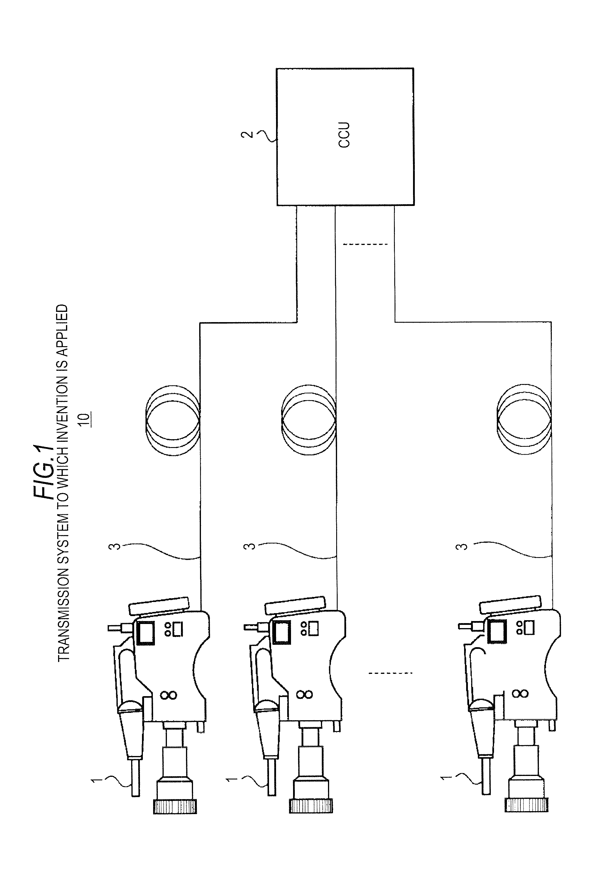
[0044]Hereinafter, a first embodiment of the invention will be explained with reference to FIG. 1 to FIG. 6C.

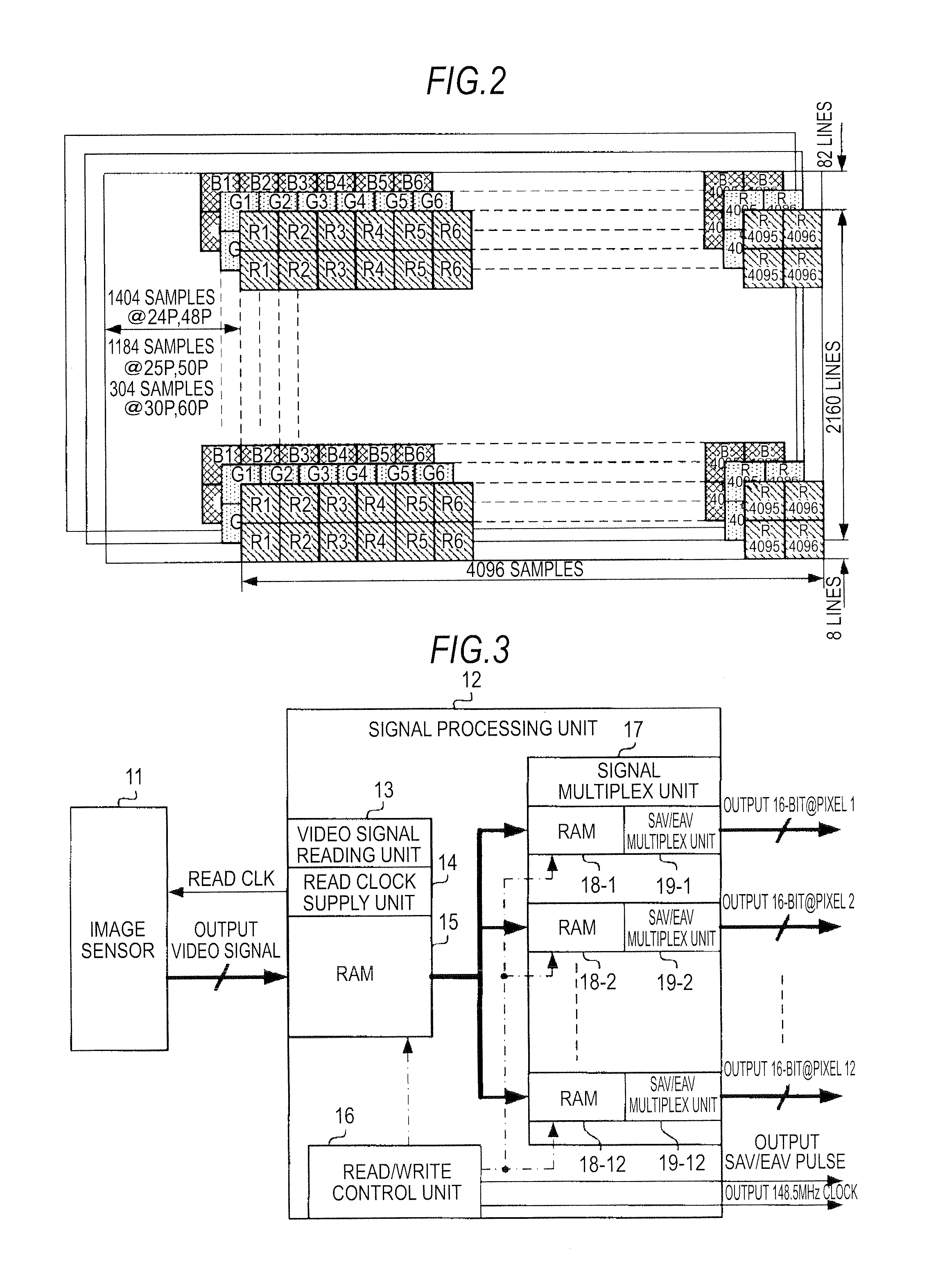
[0045]Here, the example of transmitting 4 k×2 k / 23.98 P-30 P / 4:4:4 (RGB) / 16-bit signals at 3 ch 5.94 Gbps by using a 8 B / 10 B code will be explained. In a method of thinning out pixel samples of 4096×2160 / 23.98 P, 24 P, 25 P, 29.97 P, 30 P / 4:4:4, 4:2:2 / 10-bit, 12-bit, the following abbreviations may be used. That is, 23.98 P, 24 P, 25 P, 29.97 P, 30 P is abbreviated to “23.98 P-30 P”. Also, 5.94 G is abbreviated to “6 G”. For example, a notation of “4 k×2 k / 47.95 P-60 P / 4:4:4 (RGB) / 16-bit signals” represents the following meaning. That is, the notation means that the imaging device having an RGB full pixel structure includes 4096×2160 pieces of RGB pixels and the frame rate of the image signals is 47.95-60 P, and further, the quantization bit...

second embodiment

2. SECOND EMBODIMENT

An Example of Transmitting 4 k×2 k / 47.95 P-60 P / 4:4:4 (RGB) / 16-Bit Signals at 6 ch 5.94 Gbps by Using the 8 B / 10 B Code

[0090]Next, an operation example of the camera 1 according to a second embodiment of the invention will be explained with reference to FIG. 7 to FIGS. 9A to 9C.

[0091]Here, a method of transmitting 4 k×2 k / 47.95 P-60 P / 4:4:4 (RGB) / 16-bit signals at 6 ch 5.94 Gbps by using the 8 B / 10 B code will be explained.

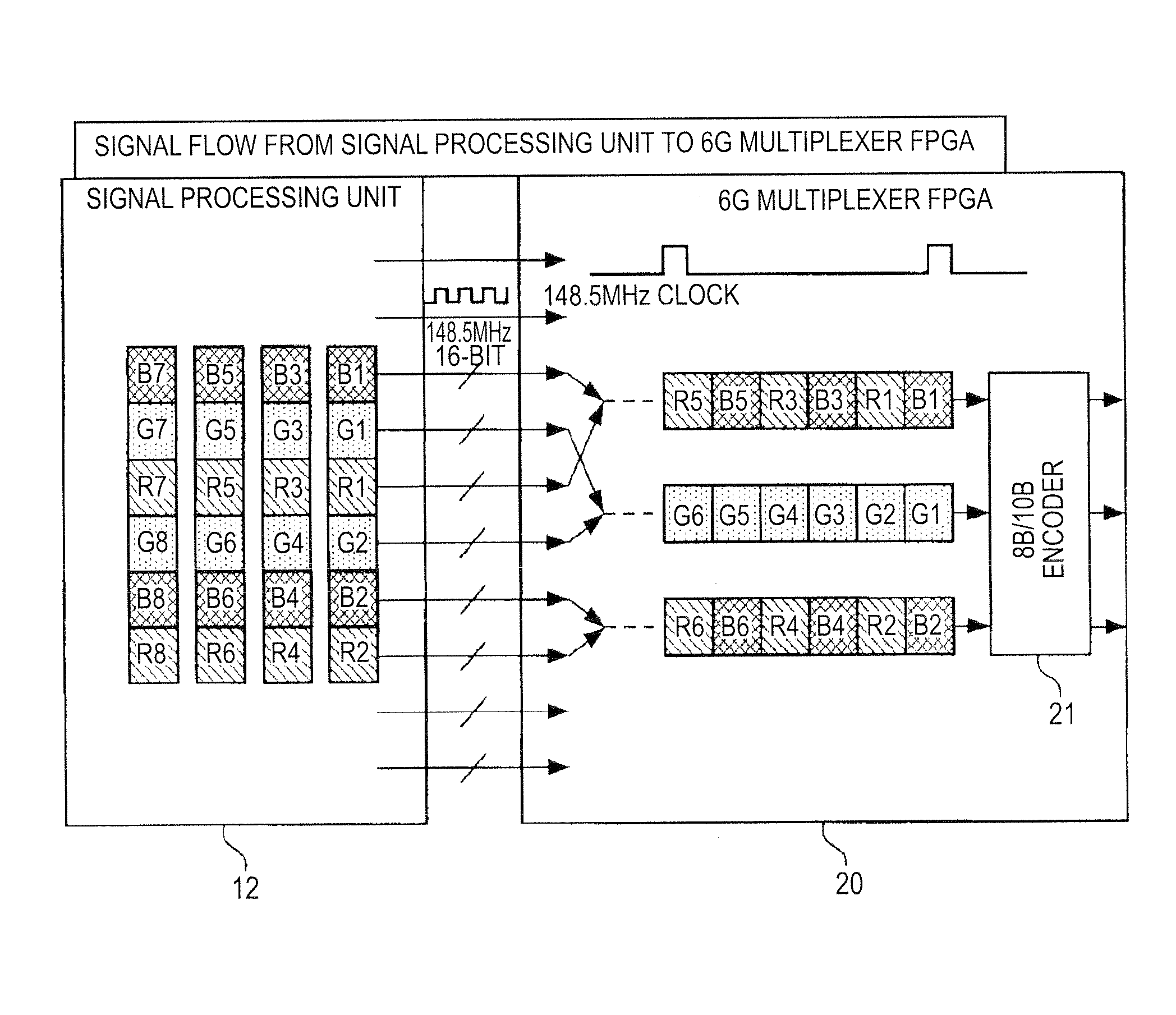
[0092]FIG. 7 shows an example of multiplexing signals in the 6 G multiplexer FPGA 20 adding given processing to 6 G R, B and G image signals received from the signal processing unit 12 and outputting the signals.

[0093]The signal processing unit 12 outputs image signals in units of R, G and B pixels. The 6 G multiplexer FPGA 20 sorts the image signals received from the signal processing unit 12 at each clock of 148.5 MHz. The timing pulse is inputted to the 6 G multiplexer FPGA 20 at every clock cycle at the timing of SAV / EAV.

[0094]The 6 G multi...

third embodiment

3. THIRD EMBODIMENT

An Example of Transmitting 4 k×2 k / 23.98 P-30 P / 4:4:4 (RGB) / 16-Bit Signals at 2 ch 10.692 Gbps by Using a 8 B / 10 B Code and Scramble

[0116]Next, an operation example of the camera 1 according to a third embodiment of the invention will be explained with reference to FIG. 10 and FIGS. 11A and 11B.

[0117]Here, a method of transmitting 4 k×2 k / 23.98 P-30 P / 4:4:4 (RGB) / 16-bit signals at 2 ch 10.692 Gbps by using the 8 B / 10 B code and scramble will be explained.

[0118]FIG. 10 shows an internal configuration example of a signal processing unit 30.

[0119]The signal processing unit 30 receives 4 k×2 k signals or signals obtained by multiplexing the signals to 3 ch 5.94 Gbps from the signal processing unit 12. Then, the signal processing unit 30 includes a TRS detection unit 31-1 detecting the multiplexed TRS from the signals having the data structure corresponding to HD-SDI in a B / R odd-numbered channel inputted from the signal multiplex unit 17. The signal processing unit 30...


PUM


Abstract

A signal transmission apparatus includes: a multiplex unit generating B / Rch by multiplexing image signals read from B, R pixels arranged in the same sample alternately on active regions corresponding to Cch in HD-SDI with a start code similar to SAV or EAV, in which image signals sequentially read in a line direction and inputted with a given number of samples from an imaging device having an RGB full pixel structure in which R, G and B pixels disposed in one sample respectively output R, G and B image signals, as well as generating Gch by sequentially multiplexing image signals read from samples of G pixels adjacent in the line direction on active regions corresponding to Ych in HD-SDI with the start code; and an 8B / 10B encoder outputting serial digital data obtained by 8B / 10B encoding and converting active regions in the B / R ch and the Gch having the data structure corresponding to HD-SDI as well as auxiliary data regions including SAV, EAV, LN and CRCC.

Description

BACKGROUND OF THE INVENTION[0001]1. Field of the Invention[0002]The present invention relates to a signal transmission apparatus and a signal transmission method suitable for being applied to a case of transmitting image signals outputted from an image sensor having, for example, an RGB full pixel structure.[0003]2. Description of the Related Art[0004]A receiving system and an imaging system of an ultra-high definition image signal which surpasses an HD (High Definition) signal which is a current image signal (video signal) of 1920 sample×1080 lines per one frame has been hitherto developed. For example, a UHDTV (Ultra High Definition TV) standard which is a next-generation broadcasting format having four-times or sixteen-times the number of pixels of the current HD is standardized in international associations. As international associations, there exist ITU (International Telecommunication Union), SMPTE (Society of Motion Picture and Television Engineers) and so on.[0005]Video stan...

Claims


Application Information

Patent Timeline
Patent Type & Authority Patents(United States)
IPC IPC(8): H04N21/242H04N7/18H04N7/12H04N21/236H04N21/2187H04N21/2665
CPCH04N21/242H04N7/181H04N21/2187H04N21/23602H04N21/2665
Inventor YAMASHITA, SHIGEYUKI
Owner SONY CORP
Why Eureka
Try Eureka