Optical attachment for reducing the focal length of an objective lens

Inactive Publication Date: 2014-12-02
CALDWELL PHOTOGRAPHIC
View PDF8 Cites 35 Cited by
  • Summary
  • Abstract
  • Description
  • Claims
  • Application Information

AI Technical Summary

Benefits of technology

[0007]It has been found that by splitting one or two of the four lens elements in the four-element structure disclosed in Publication Number US2013/0064532 into two elements, either cemented or air-spaced, that a significant improv

Problems solved by technology

Although the focal reducers described in Publication Number US2013/0064532 function well in a variety of applications, they have limitations imposed by their relatively simple structure.
Among these limitations are chromatic aberration, field curvature, a

Method used


Image

  • Optical attachment for reducing the focal length of an objective lens
  • Optical attachment for reducing the focal length of an objective lens
  • Optical attachment for reducing the focal length of an objective lens

Examples


Example

Example 1

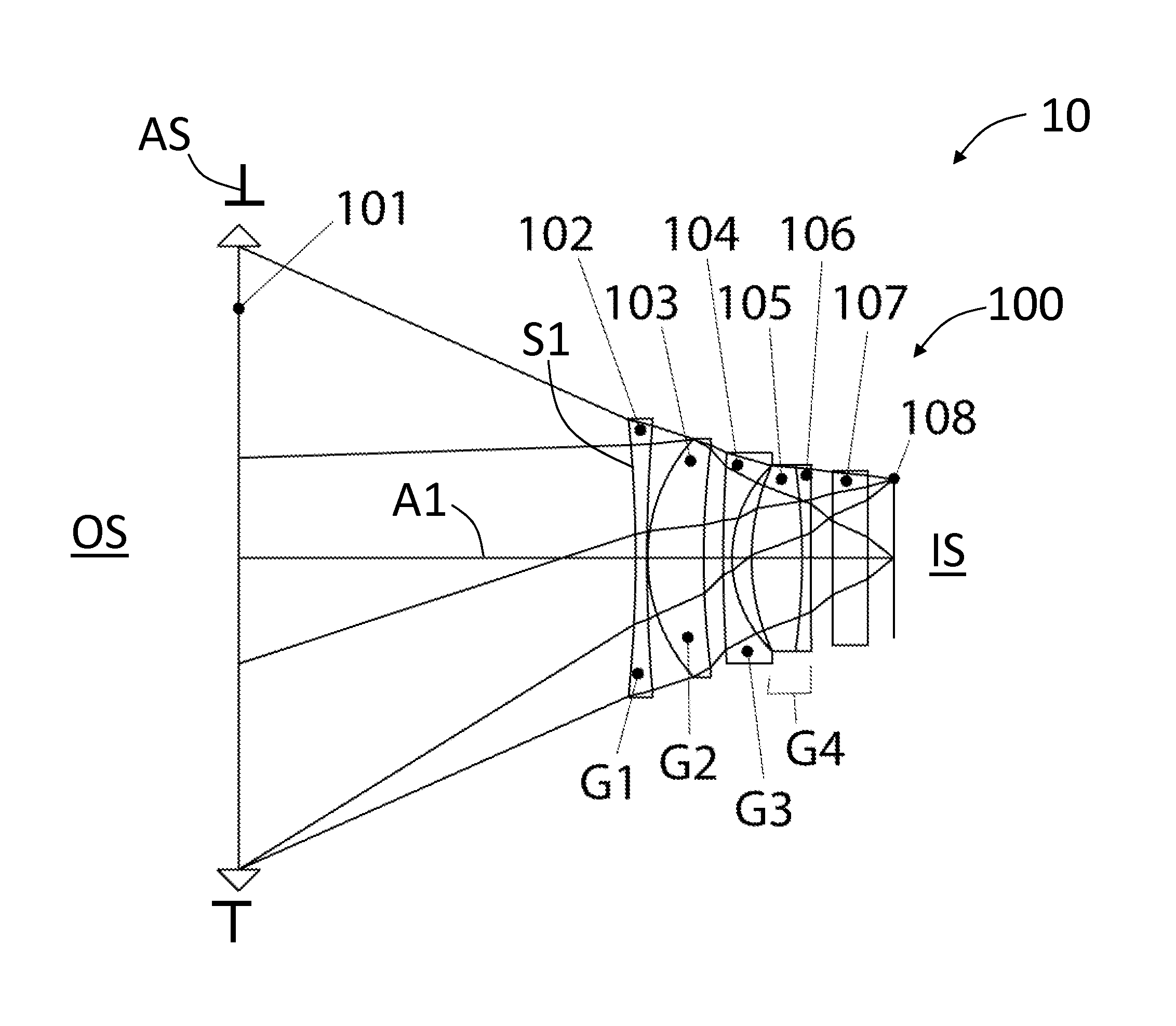
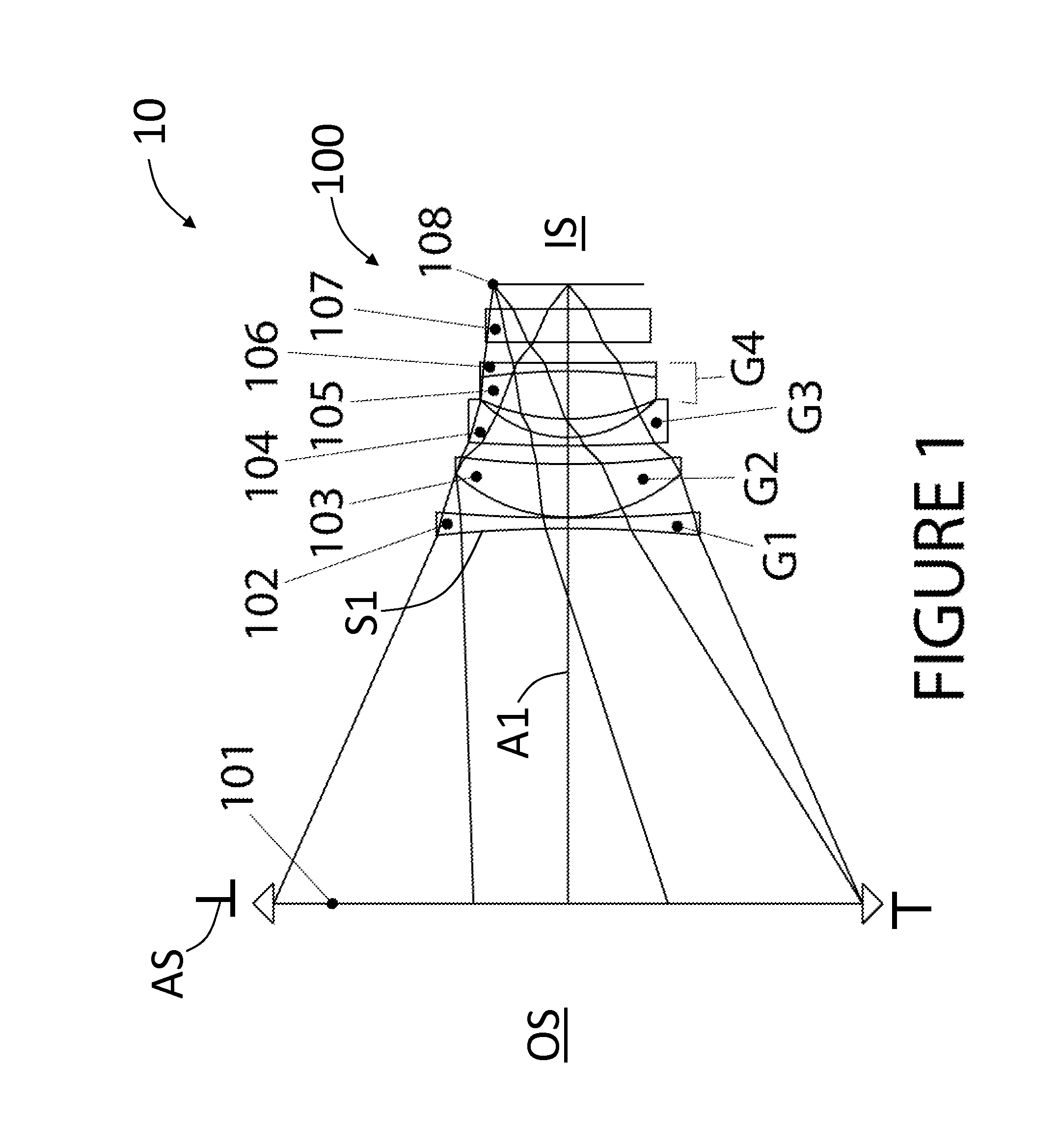
[0040]FIG. 1 is a layout of Example 1 of the present disclosure, which is an example focal-reducing attachment (“attachment”) 100 having an axis A1, an aperture stop AS, an object side OS, and an image plane 108 that defines an image side IS. The example attachment 100 has a focal length f of 65.8 mm and a magnification M of 0.64×. In order to evaluate optical performance, an objective lens 101 is included. For modeling purposes, the objective lens 101 is treated paraxially and in Example 1 has a focal length of 80 mm, with the objective lens 101 being placed 45.3 mm toward the object side OS of the attachment 100. The combination of the objective lens 101 and attachment 100 defines a lens system 10.

[0041]Although the aperture stop AS for the attachment 100 is shown as being coincident with the objective lens 101 for the purpose of aberration evaluation, it may be moved axially over a wide range of values so that it will correspond with the exit pupil location of an actual ...

Example

Example 2

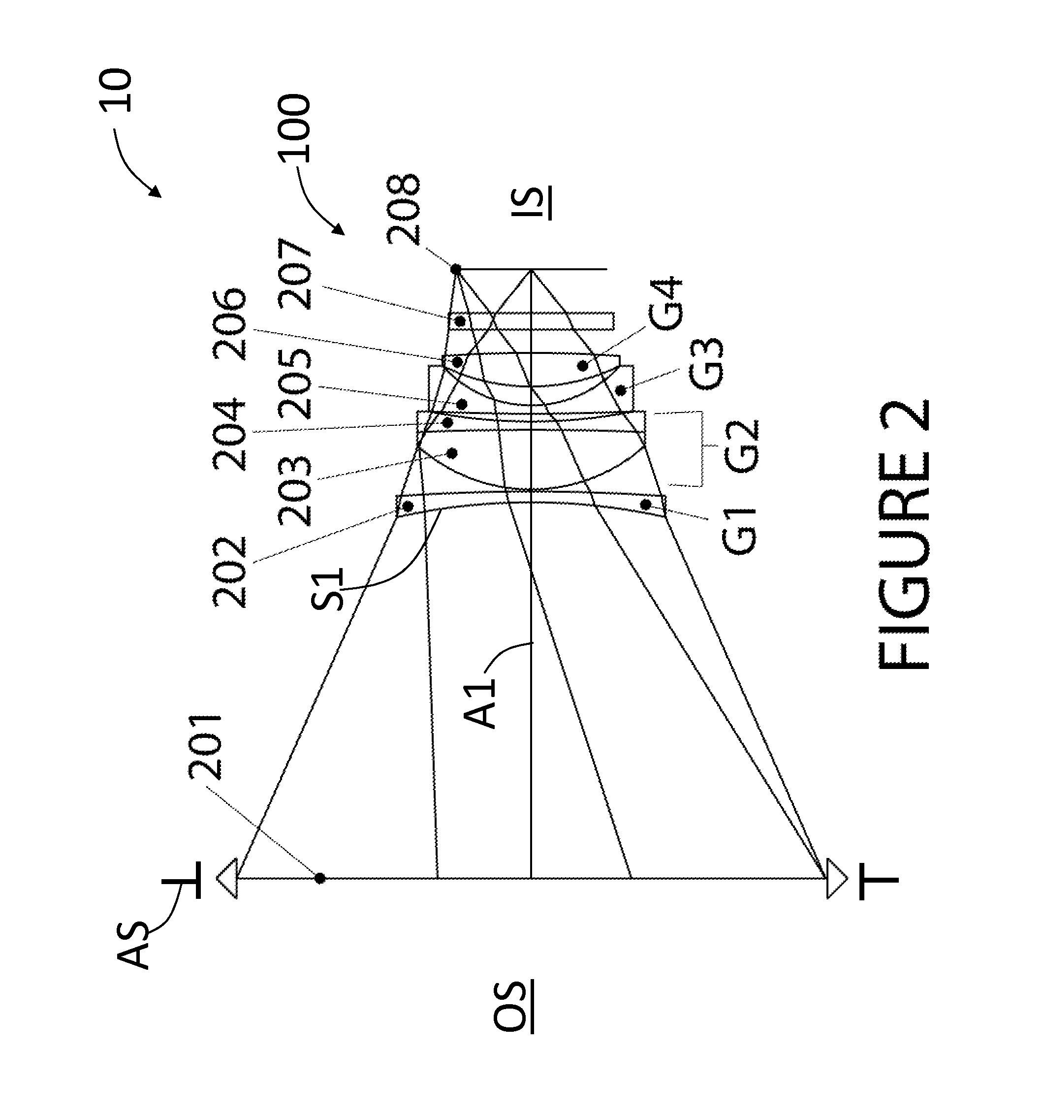
[0050]FIG. 2 is a layout of Example 2 of the present disclosure, which is an example attachment 100 having an axis A1, an aperture stop AS, an object side OS, and an image plane 208 that defines an image side IS. The example attachment 100 has a focal length f of 64.9 mm and a magnification M of 0.64×. In order to evaluate optical performance, an objective lens 201 is included. For modeling purposes, the objective lens 201 is treated paraxially and in Example 2 has a focal length of 80 mm, with the objective lens 201 being placed 45.3 mm toward the object side OS of the attachment 100. The combination of the objective lens 201 and attachment 100 defines a lens system 10.

[0051]Although the aperture stop AS for the attachment 100 is shown as being coincident with the objective lens 201 for the purpose of aberration evaluation, it may be moved axially over a wide range of values so that it will correspond with the exit pupil location of an actual attached objective lens. In pr...

Example

Example 3

[0060]FIG. 3 is a layout of Example 3 of the present disclosure, which is an example attachment 100 having an axis A1, an aperture stop AS, an object side OS, and an image plane 309 that defines an image side IS. The example attachment 100 has a focal length f of 58.1 mm and a magnification M of 0.64×. In order to evaluate optical performance, an objective lens 301 is included. For modeling purposes, the objective lens 301 is treated paraxially and in Example 3 has a focal length of 80 mm, with the objective lens 301 being placed 45.97 mm toward the object side OS of the attachment 100. The combination of the objective lens 301 and attachment 100 defines a lens system 10.

[0061]Although the aperture stop AS for the attachment 100 is shown as being coincident with the objective lens 301 for the purpose of aberration evaluation, it may be moved axially over a wide range of values so that it will correspond with the exit pupil location of an actual attached objective lens. In p...


PUM


Abstract

An optical attachment having five or six elements and configured to be operably arranged on the image side of an objective lens to reduce the focal length and focal ratio of the objective lens is disclosed. The optical attachment is particularly suitable for adapting objective lenses designed with a relatively large working distance for a large format size to cameras having a smaller format size and relatively small permissible working distance. The optical attachments disclosed herein have high image quality at large aperture over a large field of view, and can be well-corrected for all major aberrations.

Description

CROSS-REFERENCE TO RELATED APPLICATIONS[0001]This application claims priority under 35 USC 119 from U.S. Provisional Patent Application Ser. No. 61 / 862,294, filed on Aug. 5, 2014, and which is incorporated by reference herein.[0002]This application is related to U.S. Pre-Grant Pub. No. US2013 / 0064532, which has U.S. Patent App. Ser. No. 61 / 589,880, and which is entitled “Optical Attachment for Reducing the Focal Length of an Objective Lens,” and which is incorporated herein by reference.[0003]The entire disclosure of any publication or patent document mentioned herein is incorporated by reference.FIELD[0004]The present disclosure is directed to an optical attachment placed on the image side of an objective lens in order to reduce the focal length and focal ratio of that objective lens. The present disclosure is particularly suitable for adapting objective lenses designed with a relatively large working distance for a large format size to cameras having a smaller format size and rela...

Claims


Application Information

Patent Timeline
IPC IPC(8): G03B17/14G02B9/00G03B17/56
CPCG03B17/565G02B9/00G02B9/34G02B15/10
Inventor CALDWELL, J. BRIAN
Owner CALDWELL PHOTOGRAPHIC
Why Eureka
Try Eureka