Control apparatus for power unit

a technology of control apparatus and power unit, which is applied in the direction of engines/engines, propulsion parts, and propulsion using engine-driven generators. it can solve the problems of deterioration of fuel economy, inability to sufficiently purify components to be purified by catalysts, and inability to achieve catalyst purification. the effect of catalyst purification

Active Publication Date: 2014-12-09
TOYOTA JIDOSHA KK
View PDF3 Cites 8 Cited by
  • Summary
  • Abstract
  • Description
  • Claims
  • Application Information

AI Technical Summary

Benefits of technology

[0010]Thus, the invention of the present application provides a control apparatus for a power unit that holds the purification capacity of a catalyst high while suppressing a deterioration in fuel economy and preventing a sense of discomfort from being caused to a driver.

Problems solved by technology

However, if engine operation has already been started when the purification rate of the catalyst is equal to or lower than the aforementioned predetermined value during the performance of engine start / stop control, the power output unit prohibits the engine operation from being stopped and continues the engine operation.
Then, when this gas containing a large amount of oxygen flows into the catalyst, the catalyst may deteriorate.
It should be noted herein that if the catalyst deteriorates when the purification rate of the catalyst is relatively low, it is impossible to sufficiently purify components to be purified by the catalyst when the exhaust gas containing the components flows into the catalyst.
Therefore, fuel is consumed correspondingly, and as a result, a deterioration in fuel economy is caused.
Further, in the case where the power output unit is mounted on a vehicle and is designed to start and stop engine operation in accordance with a request made by a driver of the vehicle, if the power output unit starts engine operation as in the case of the power output unit described in Japanese Patent Application Publication No. 2004-124827 (JP-2004-124827 A) when the purification rate of the catalyst is lower than the aforementioned predetermined value, a sense of discomfort may be caused to the driver.

Method used


Image

  • Control apparatus for power unit
  • Control apparatus for power unit
  • Control apparatus for power unit

Examples


first embodiment

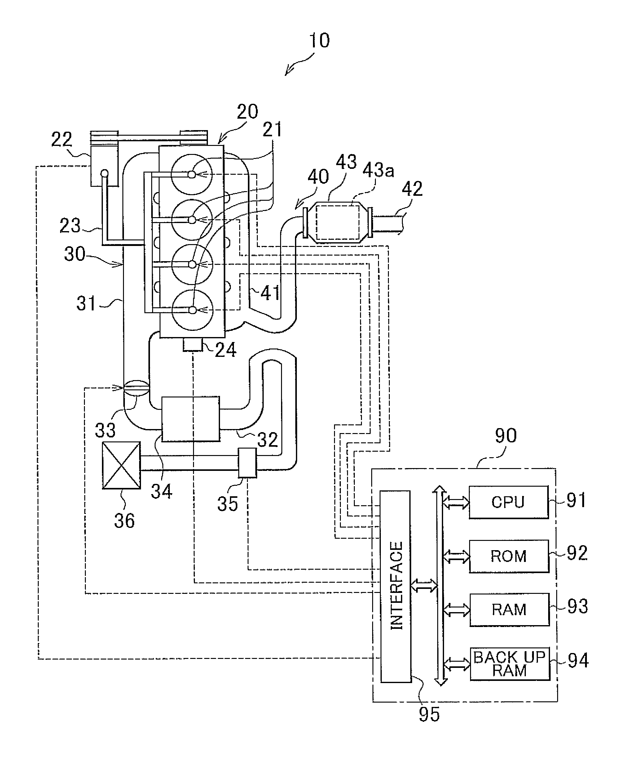
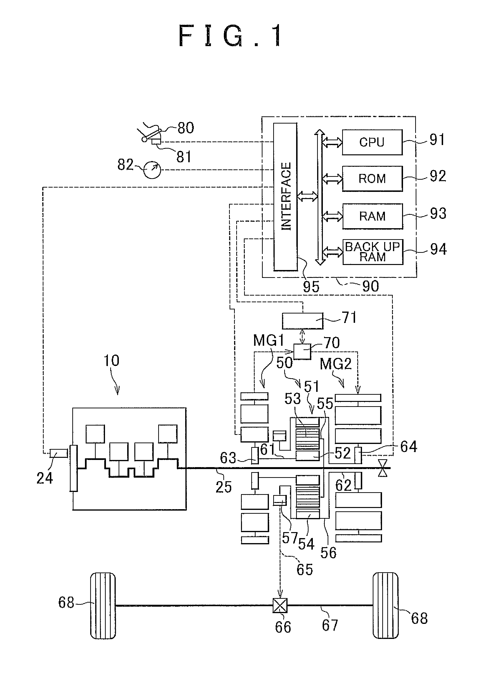
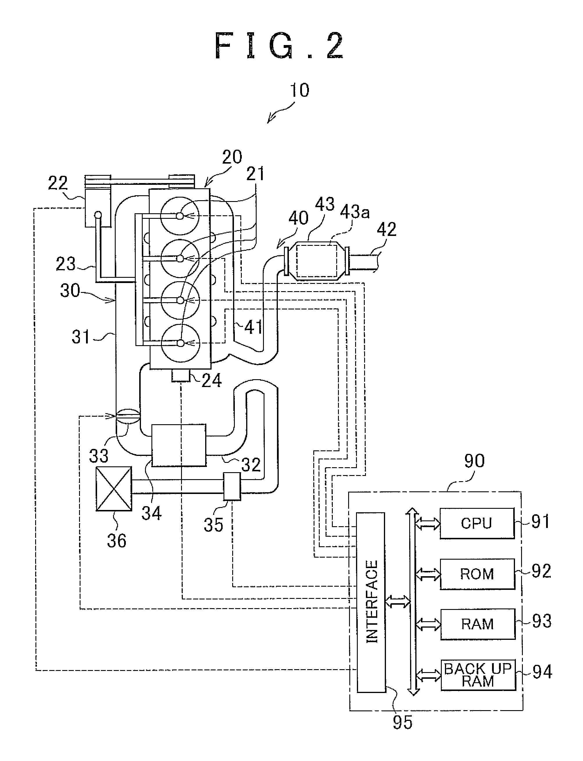
[0061]The accelerator pedal depression stroke sensor 81 is electrically connected to the interface 95 of the electronic control unit 90. The accelerator pedal depression stroke sensor 81 outputs an output value corresponding to a depression stroke of the accelerator pedal 80. This output value is input to the electronic control unit 90. On the basis of this output value, the electronic control unit 90 calculates a depression stroke of the accelerator pedal 80, and hence an output required of the power unit. It should be noted that the power unit according to the invention is generally composed of the internal combustion engine 10, the first generator motor MG1, and the second generator motor MG2.

[0062]Next, the control of the power unit according to the first embodiment of the invention will be described. Incidentally, in the following description, “an output power” means “a power output from the power unit”. “A required power” means “an output power that is required to be output fr...

second embodiment

[0106]It should be noted in the invention that the engine stop threshold that is set when the purification capacity of the catalyst is lower than the stop threshold correction threshold may be a value smaller than the reference engine stop threshold. Accordingly, for example, a value that is smaller than the reference engine stop threshold by a certain value regardless of the purification capacity of the catalyst may be set as the engine stop threshold, a value that decreases as the purification capacity of the catalyst decreases with respect to the stop threshold correction threshold may be set as the engine stop threshold (in this case, the set engine stop threshold is a value that monotonically decreases as the purification capacity of the catalyst decreases with respect to the stop threshold correction threshold), or a value that stepwise decreases as the purification capacity of the catalyst decreases with respect to the stop threshold correction threshold may be set as the eng...

third embodiment

[0123]Further, in the invention, the start threshold correction threshold and the stop threshold correction threshold may be equal to each other, or may be different from each other.

[0124]For a reason similar to the reason described in relation to the first embodiment of the invention and the second embodiment of the invention, the third embodiment of the invention is advantageous in that the purification capacity of the catalyst can be held high while suppressing a deterioration in fuel economy (in other words, reducing the amount of fuel consumed by the internal combustion engine) and preventing a sense of discomfort from being caused to the driver of the hybrid vehicle. Furthermore, in the third embodiment of the invention, a value smaller than the reference engine start threshold is set as the engine start threshold when the purification capacity of the catalyst is lower than the start threshold correction threshold, and a value smaller than the reference engine stop threshold i...


PUM


Abstract

A control apparatus for a power unit equipped with an internal combustion engine and outputs a power. The control apparatus according to the invention starts engine operation when the required power becomes equal to or larger than an engine start threshold during engine stop, and stops engine operation when the required power becomes equal to or smaller than an engine stop threshold during engine operation. The internal combustion engine is equipped with a catalyst. When the purification capacity of the catalyst is lower than a start threshold correction threshold, a value smaller than a reference engine start threshold is set as the engine start threshold. When the purification capacity of the catalyst is equal to or higher than the start threshold correction threshold, a value equal to the reference engine start threshold or a value larger than the reference engine start threshold is set as the engine start threshold.

Description

CROSS REFERENCE TO RELATED APPLICATIONS[0001]This application claims priority to Japanese Patent Application No. 2011-162779 filed on Jul. 26, 2011, which is incorporated herein by reference in its entirety including the specification, drawings and abstract.BACKGROUND OF THE INVENTION[0002]1. Field of the Invention[0003]The invention relates to a control apparatus for a power unit.[0004]2. Description of Related Art[0005]A power output unit that is provided with an internal combustion engine equipped with a catalyst that purifies components in exhaust gas discharged from a combustion chamber is described in Japanese Patent Application Publication No. 2004-124827 (JP-2004-124827 A). This power output unit is configured to be capable of performing the control (this control will be referred to hereinafter as “engine start / stop control) of starting and stopping the operation of the internal combustion engine (this operation will be referred to hereinafter as “engine operation”). Besides...

Claims


Application Information

Patent Timeline
Patent Type & Authority Patents(United States)
IPC IPC(8): B60W20/00B60W10/06F01N3/18B60K6/445F02N11/08F02D41/02B60L50/16
CPCB60W20/00F02N2200/026F02N11/0822B60K6/445B60W10/06Y02T10/48F02N11/0829Y02T10/6239F02D41/0235Y02T10/54B60L2240/36B60L2240/423B60L2240/443B60L2260/26Y02T10/40Y02T10/62Y02T10/64
Inventor AMANO, TAKASHI
Owner TOYOTA JIDOSHA KK
Why Eureka
Try Eureka