Turbine bucket lockwire rotation prevention

a technology of rotating prevention and bucket lockwire, which is applied in the direction of liquid fuel engines, marine propulsion, and vessels to avoid collisions with neighboring stationary components, and can solve problems such as oxidation erosion, wear away the leading edge of the blade, and the tendency of the blade to move along the dovetail

Active Publication Date: 2014-12-09
GE INFRASTRUCTURE TECH INT LLC
View PDF31 Cites 7 Cited by
  • Summary
  • Abstract
  • Description
  • Claims
  • Application Information

AI Technical Summary

Benefits of technology

[0007]In one exemplary but nonlimiting embodiment, the invention relates to a retention system for a plurality of turbine buckets located in respective mating slots in a turbine rotor wheel, the retention system comprising a plurality of first circumferentially-oriented retention slots formed in outer peripheral portions of the turbine wheel; a plurality of second circumferentially-oriented retention slots formed in wheel mounting portions of the buckets, the first and second retention slots aligned to form an annular lockwire retention slot; a lockwire located within the annular lockwire retention slot, the lockwire having free ends; a first surface feature on one or both of the turbine rotor wheel and one or more of the plurality of turbine buckets; and a second surface feature on the lockwire adapted to engage with the first surface feature on one or both of the turbine rotor wheel and one or more of the plurality of turbine buckets for preventing circumferential rotation of the lockwire beyond predetermined limits.
[0008]In a second exemplary but nonlimiting embodiment, the invention relates to a retention system for a plurality of turbine buckets located in respective mating slots in a turbine rotor wheel, the retention system comprising a plurality of first circumferentially-oriented retention slots formed in outer peripheral portions of the turbine wheel; a plurality of second circumferentially-oriented retention slots formed in wheel mounting portions of the buckets, the first and second retention slots aligned to form an annular lockwire retention slot; a lockwire located within the annular lockwire retention slot, the lockwire having free ends; at least one axially-oriented surface feature provided on the rotor wheel or on one or more of the plurality of buckets for holding the lockwire in the annular retention slot; and at least one radially extending surface feature on the lockwire engageable with the at least one axially-oriented surface feature for preventing circumferential rotation of the lockwire beyond predetermined limits.
[0009]In still another nonlimiting aspect, the invention relates to a retention system for a plurality of turbine buckets located in respective mating slots in a turbine rotor wheel, the retention system comprising a plurality of first circumferentially-oriented retention slots formed in outer peripheral portions of the turbine wheel; a plurality of second circumferentially-oriented retention slots formed in wheel mounting portions of the buckets, the first and second retention slots aligned to form an annular lockwire retention slot; a lockwire located within the annular lockwire retention slot, the lockwire having free ends; at least one surface feature provided on the rotor wheel or on one or more of the plurality of buckets for holding the lockwire in the annular retention slot; and at least one axially-extending surface feature on the lockwire engageable with the at least one surface feature on the rotor wheel or on one or more of the plurality of buckets for preventing circumferential rotation of the lockwire beyond predetermined limits.

Problems solved by technology

However, operation at low speed, during which the blades are able to rock inside the dovetail, can have the tendency to make the blade move along the dovetail in the absence of axial retention.
If the blade is not properly retained, the eventual likely outcome is a collision with neighboring stationary components.
In the absence of the cooling flow, oxidation erosion will wear away the leading edge of the blade.
An additional consequence, therefore, is unplanned machine down-time and maintenance resulting from varying degrees of machine performance deterioration up to blade separation and resulting collateral or domestic object damage.
Without the lockwire, the airfoils are free to travel axially along the dovetail slots, creating the potential for excessive wear and interference as mentioned above.
When these holes are blocked due to axial movement of the bucket, cooling air cannot reach the target area and the bucket can quickly oxidize along the leading edge.

Method used


Image

  • Turbine bucket lockwire rotation prevention
  • Turbine bucket lockwire rotation prevention
  • Turbine bucket lockwire rotation prevention

Examples


Embodiment Construction

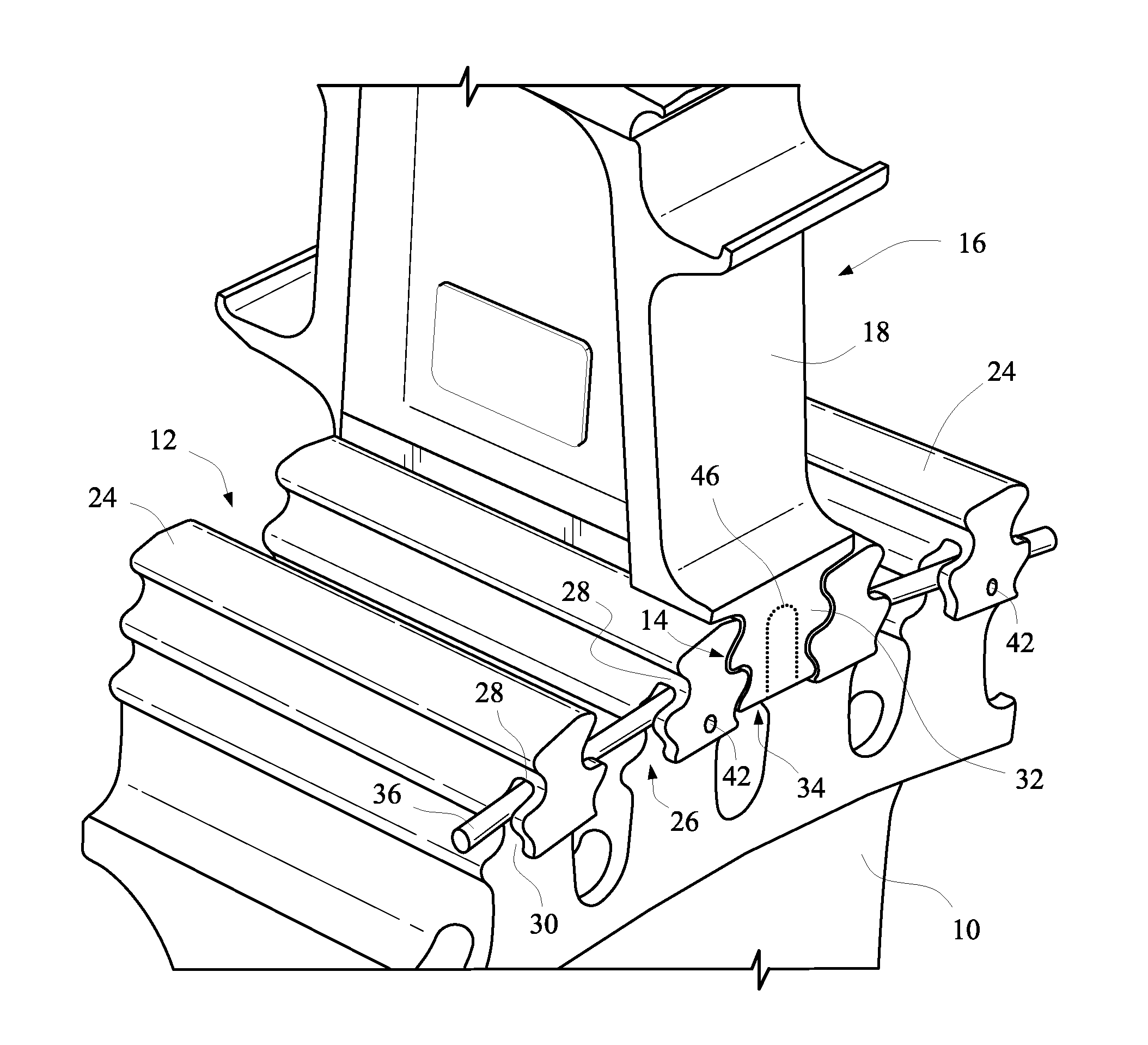
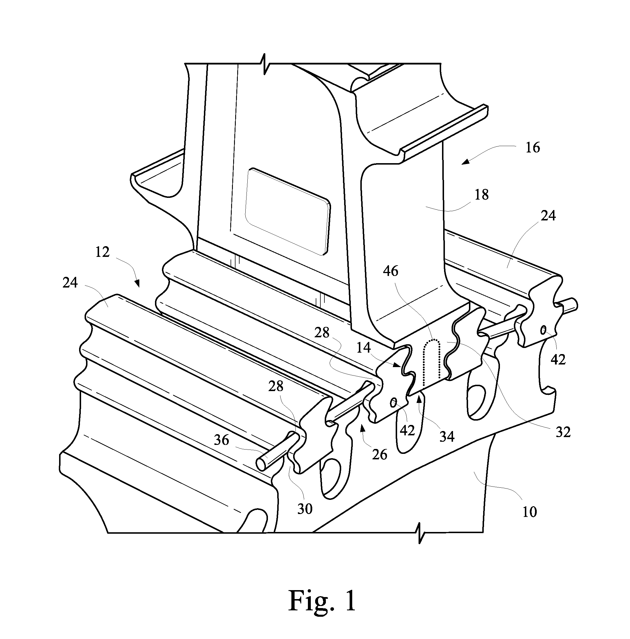
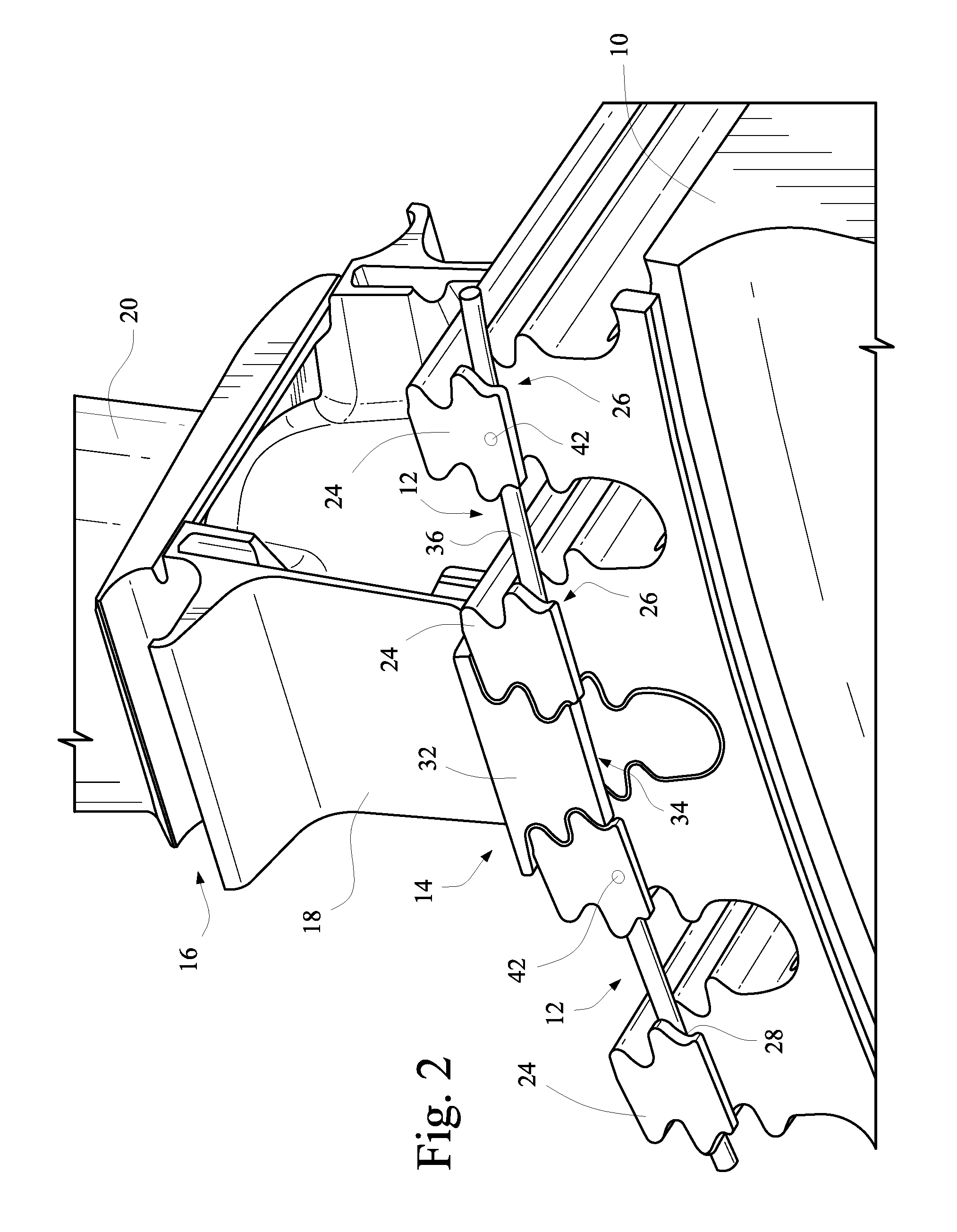
[0022]FIGS. 1 and 2 illustrate one technique for preventing axial movement of a turbine bucket received within a slot in a turbine rotor wheel. More specifically, the turbine rotor wheel 10 is formed with a plurality of dovetail slots 12 about the entire outer periphery of the wheel, each dovetail slot 12 receiving a complementary dovetail portion 14 of a bucket or blade 16 (only three complete slots and one bucket shown in the Figures). It will be understood that the bucket or blade 16 is of conventional construction, including a shank portion 18, an airfoil portion 20 and the dovetail portion (or simply, dovetail) 14.

[0023]The radially projecting portions 24 of the wheel which define the slots 12 are formed with first lockwire slots 26, each closed at its radially outer end 28 and open at its radially inner end 30. The first lockwire slots 26 are formed adjacent to one side of the wheel, and together, form an annular 360° slot about the periphery of the wheel, interrupted by the d...


PUM


Abstract

A retention system for a plurality of turbine buckets located in respective mating slots in a turbine rotor wheel includes a plurality of first circumferentially-oriented retention slots formed in outer peripheral portions of the turbine wheel; a plurality of second circumferentially-oriented retention slots formed in wheel mounting portions of said buckets, the first and second circumferentially-oriented retention slots aligned to form an annular lockwire retention slot; and a lockwire located within the annular lockwire retention slot. A first surface feature on one or both of the turbine rotor wheel and one or more of said plurality of turbine buckets is adapted to engage a second surface feature on the lockwire for preventing rotation of the lockwire beyond predetermined limits.

Description

BACKGROUND OF THE INVENTION[0001]The invention relates to a retention system used to prevent axial movement of a turbine bucket dovetail in a corresponding dovetail slot in a turbine rotor wheel, and more specifically, to techniques for preventing circumferential rotation of the axial retention system. This retention system typically takes the form of a lockwire within an annular slot or groove in the turbine rotor wheel.[0002]In conventional turbine and / or turbine compressor components, buckets (or blades, or airfoils) are held in a rotor wheel by means of a slotted connection, e.g., a so-called “fir tree” or “Christmas tree” arrangement where an inwardly-tapered male connector portion at the radially inner end of the bucket is received in a complementary female slot in the rotor wheel. Such connections are also generically referred to as “dovetail” connections, embracing various complementary shapes which lock the buckets to the wheel in the radial and circumferential directions s...

Claims


Application Information

Patent Timeline
Patent Type & Authority Patents(United States)
IPC IPC(8): F01D5/32F01D5/02F01D5/30
CPCF01D5/326F01D5/3007
Inventor ROMAN-MORALES, FELIPEJACALA, ARIEL CAESAR PREPENAXU, LIMINGMYERS, MELBOURNE JAMESBRUCE, KEVIN LEONAMMANN, LUKE JOHN
Owner GE INFRASTRUCTURE TECH INT LLC
Why Eureka
Try Eureka