
PWM frequency pattern optimization for NVH

a technology of pwm frequency pattern and nvh, which is applied in the direction of dynamo-electric motor/converter starter, amplitude demodulation details, error prevention, etc., can solve the problems of reducing the fuel efficiency of electric or hybrid electric vehicles, affecting the operation of switching at frequencies within the audible spectrum can produce unpleasant high-pitched whining and whistling noises that irritate automobile operators and passengers, etc. to optimiz

Active Publication Date: 2014-12-09
FORD GLOBAL TECH LLC
View PDF11 Cites 8 Cited by
  • Summary
  • Abstract
  • Description
  • Claims
  • Application Information

AI Technical Summary

Benefits of technology

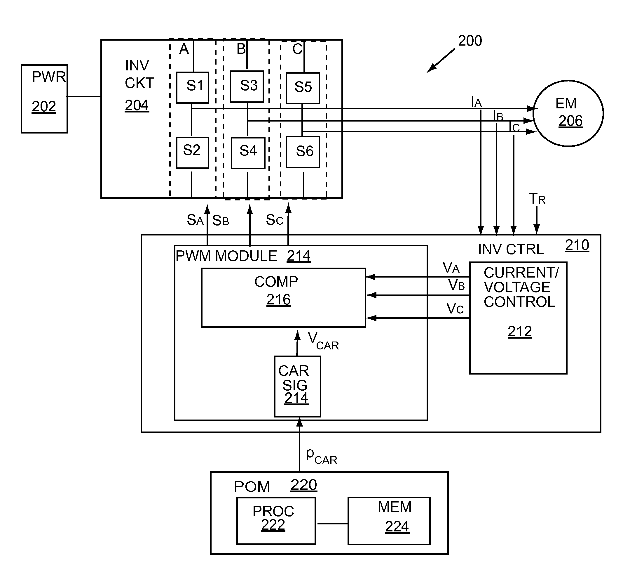
The patent is about a system that optimizes the use of PWM energy in an electric drive system to reduce noise. It uses an optimized pattern of pulses to spread the noise energy in the frequency spectrum and reduce the noise audible to car operators or passengers. The system also includes an inverter circuit that uses the optimized PWM drive signal. The system can change the carrier period of the signal at half-periodes or full periods, and can be designed independently of the electric machine's current and torque requirements. The technical effects of this system are reduced noise in the electric drive system and improved performance.

Problems solved by technology

However, switching at frequencies within the audible spectrum can produce unpleasant high pitched whining and whistling noises that irritate automobile operators and passengers.
While employing a carrier frequency of 7.5 kHz can move the switching frequency to the upper end of the audible range where the human ear is less sensitive, the higher switching frequency can result in higher switching losses, which can decrease fuel efficiency for an electric or hybrid electric vehicle.
Other solutions, such as randomization of incremental frequencies around 7.5 kHz, such as 7.75 kHz and 7.25 kHz, help mitigate switching noise, but increase switching losses and decrease fuel economy.

Method used


Image

  • PWM frequency pattern optimization for NVH
  • PWM frequency pattern optimization for NVH
  • PWM frequency pattern optimization for NVH

Examples


Embodiment Construction

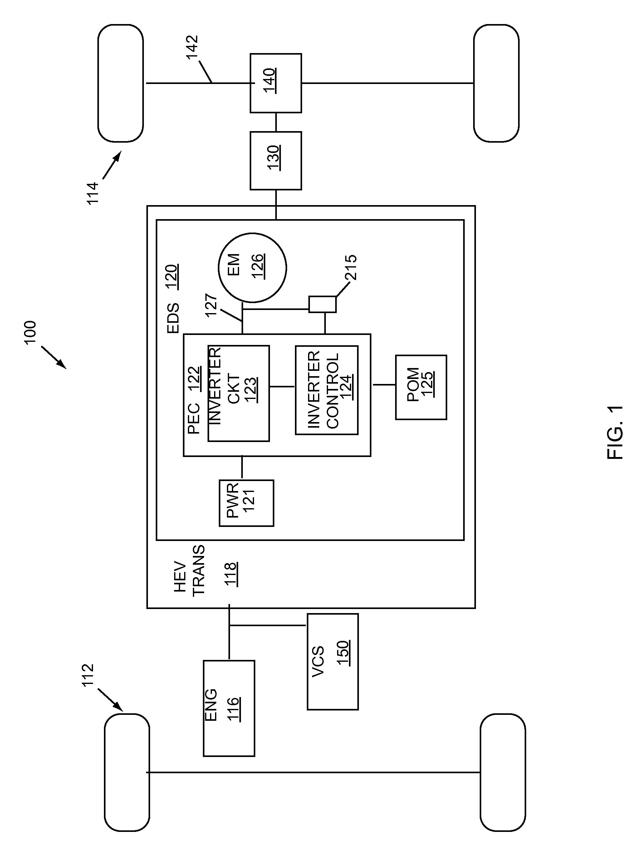
[0017]Example embodiments of the invention are presented herein; however, the invention may be embodied in a variety of alternative forms, as will be apparent to those skilled in the art. To facilitate understanding of the invention, and provide a basis for the claims, various figures are included in the description. The figures are not drawn to scale and related elements may be omitted so as to emphasize the novel features of the invention. Structural and functional details depicted in the figures are provided for the purpose of teaching the practice of the invention to those skilled in the art and are not to be interpreted as limitations. For example, control modules and components for various systems can be variously arranged and / or combined, and are not to be considered limited to the example configurations presented herein. The invention will be explained in the context of a vehicle having a powertrain that includes an electric machine, however it is understood that the inventi...


PUM


Abstract

An optimized pseudo-random period pattern can reduce audible noise in a system that includes an inverter circuit configured to provide power to an electric machine. A system can include a PWM optimization module (POM) comprising the PPP. A carrier period for a carrier signal used to provide PWM inverter drive signals can be selected in accordance with the PPP. The PPP can be expressed as an array of 200-400 elements, each element a period belonging to a finite set of 2 or more predetermined periods. A period can be selected by index from the array, and the index incremented to progress through the PPP, which can be repeated upon its completion. The PPP can be optimized to reduce audible noise while mitigating inverter losses. Modeling techniques can determine the number of array elements, the number of possible periods, and the period values that optimize the PPP.

Description

BACKGROUND OF INVENTION[0001]1. Field of Invention[0002]This invention relates generally to power electronic inverter systems, and more particularly to methods and apparatus to reduce noise, vibration and harshness (NVH) associated with an electric machine for a vehicle.[0003]2. Background Art[0004]Electric and hybrid electric vehicles can employ electrical energy for propulsion via an electric drive system that can include a power circuit, such as a power electronics inverter, coupled to an electric machine. In this arrangement, the power circuit can control the transfer of power between a power source and the electric machine to drive a load, such as the vehicle transaxle. For a three-phase, AC electric machine, the power circuit can include an inverter with three phase legs, each leg comprising switches that can be individually controlled to provide a desired inverter output. As an example, drive signals that are a function of an electric machine's torque requirement can be provi...

Claims


Application Information

Patent Timeline
Patent Type & Authority Patents(United States)
IPC IPC(8): H02K29/06
CPCB60L2240/526H02M1/44H02M7/5395B60L2270/142
Inventor MILLER, JAMI J.DEGNER, MICHAEL W.YU, SCOTT XIONGREYNOLDS, WILLIAM C.
Owner FORD GLOBAL TECH LLC
Learn More