Methods and devices for transmitting and receiving data signals in a wireless network over a plurality of transmission paths

a wireless network and transmission path technology, applied in the field of wireless communication, can solve the problems of difficult implementation of searching for/updating the set of all possible transmission paths, associate a reliable transmission, and inability to quickly determine etc., to achieve the highest level of reception quality, increase spatial diversity, and quickly check the validity of transmission paths

Active Publication Date: 2014-12-09
CANON KK
View PDF16 Cites 3 Cited by
  • Summary
  • Abstract
  • Description
  • Claims
  • Application Information

AI Technical Summary

Benefits of technology

[0045]This allows the first device to know which transmission path to use in each communication time slot when emitting data signals. This provides a great flexibility for the second device to select the appropriate transmission paths to be used at each cycle with the possibility of modifying them from one cycle to another, either because some transmission paths are no longer valid and / or for increasing spatial diversity. This has also the advantage of quickly checking the validity of transmission paths in each cycle before data signals emission.
[0046]Thus, the second device takes profit of each configuring sub-slot for trying different transmission paths corresponding to predetermined receiving antenna configurations (i.e. orientation angle sets) and identifying valid transmission paths. In a particular embodiment, the second device selects, among the identified receiving antenna configurations, the one for which the level of reception quality is the highest. Therefore it is possible to maintain high quality communications of data between the transmitter and the receiver during the communication time slots.
[0047]Advantageously, if the number of identified valid transmission paths is greater than the number of communication slots (M), the selection list is built by selecting M distinct valid transmission paths. Otherwise, the selection list is built by selecting all the identified valid transmission paths and re-selecting as much as possible of distinct valid transmission paths so that to form a selection list of M transmission paths. This allows to ensure a spatial diversity.
[0049]In a preferred embodiment of the invention, the emitting of the reference signal by the first device is performed in all possible directions by using a wide beam or omnidirectional sender antenna. This has the advantage of allowing the possible discovery of new transmission path by the second device if it performs a search in other directions than those corresponding to the already identified K transmission paths
[0065]This has the advantage to take profit of one or several additional time slots for performing a full scan of the 3D space in order to give time to the first device to discover new transmission paths to use. It has also the advantage when no transmission path is identified, and as no communication can be performed in point-to-point mode, to dedicate the available for searching new transmission paths.

Problems solved by technology

This problem becomes critical when very short time is available for finding and / or agreeing on the transmission path to use.
Indeed, even if a full scan is performed in three dimensions for searching for all possible paths beforehand, these transmission paths may not be available or valid when the communication actually starts because of the moving obstacles that may interrupt the communication or because the objects 115 over which signals are reflected have been displaced.
A difficulty is then to be able to swiftly determine and associate a reliable transmission path with each time slot.
Moreover, using an antenna beam that is steerable in three dimensions (3D) advantageously increases the chances of finding many transmission paths (all objects including walls, ceiling and floor can then be acting as reflecting objects 115), but at the same time renders the implementation of searching for / updating of the set of all possible transmission paths more difficult because of the required time for doing the search.

Method used


Image

  • Methods and devices for transmitting and receiving data signals in a wireless network over a plurality of transmission paths
  • Methods and devices for transmitting and receiving data signals in a wireless network over a plurality of transmission paths
  • Methods and devices for transmitting and receiving data signals in a wireless network over a plurality of transmission paths

Examples


Embodiment Construction

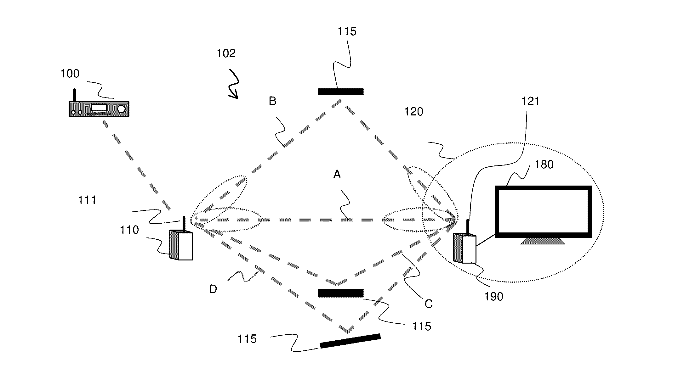
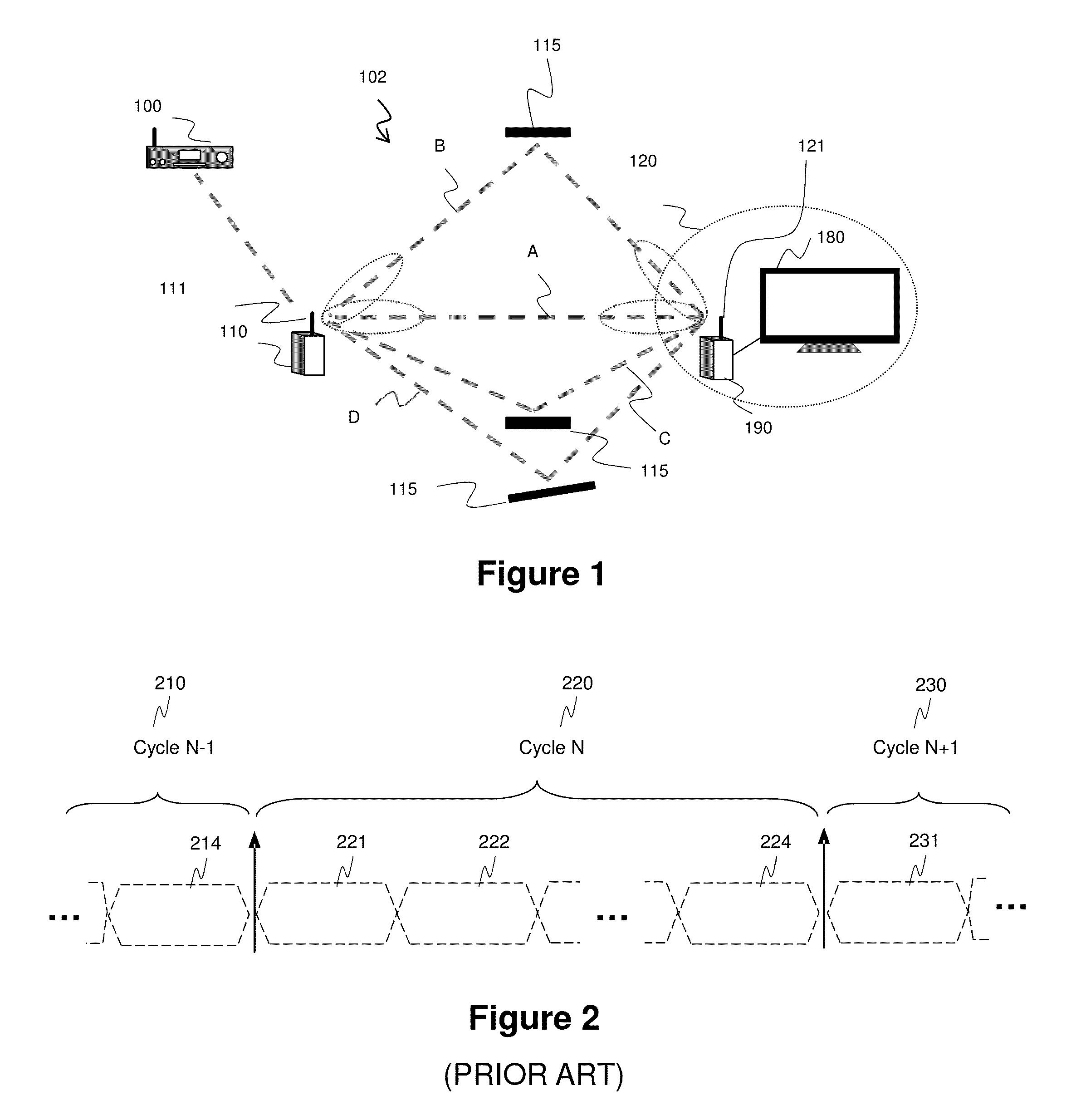
[0084]The invention is described, in at least one of its embodiments, by considering the example of the wireless network of FIG. 1. In this wireless network, first device 110 represents the data source node and second device 120 represents the data destination node. The invention is of course not limited to this particular example and may apply to any number of pairs of communicating devices. The invention is also applicable if the first device 110 is acting as a data relay node.

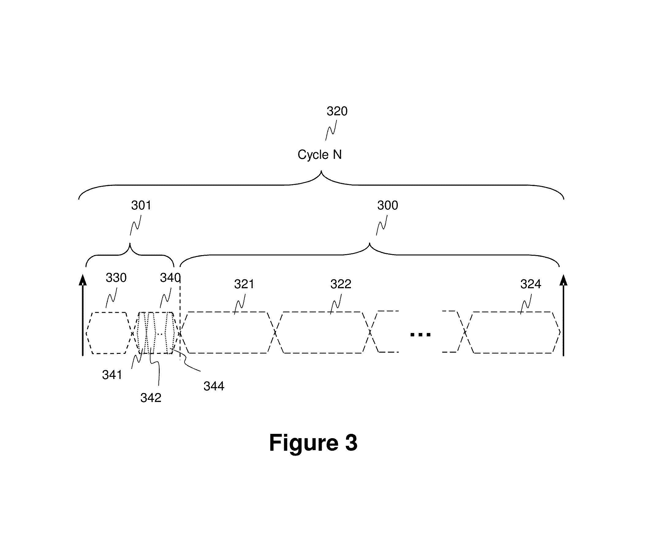
[0085]FIG. 3 illustrates a TDM scheme that is used for implementing an embodiment of the invention.

[0086]Time domain is divided into a plurality of successive network cycles 320 (N, N+1, . . . ) (they can also be referred to as frames). The start of a cycle is signaled to all devices of the network by a beacon signal emitted by a central device (master) that can be a distinct device or one of the communication devices 100, 110 or 120. Each communication cycle 320 is further divided into a configuration perio...


PUM


Abstract

A method includes emitting a reference signal following K transmission paths during a first configuration time slot, identifying valid transmission paths among the set of K transmission paths by listening, according to each transmission path of the set, for a feedback reference signal from the second device during the second configuration time slot; and emitting data signals in each communication time slot of which the associated transmission path has been identified as valid.

Description

BACKGROUND OF THE INVENTION[0001]The present invention relates to the field of wireless communication. The present invention especially relates to a method of transmitting data signals, a method of receiving data signals, a first device for transmitting data signals and a second device for receiving data signals.[0002]FIG. 1 depicts for illustrative purposes a wireless communication network 102 employing spatial diversity relying on the use of a plurality of transmission paths between communicating devices. More particularly, network 102 illustrates a 60 GHz (millimeter band) radio transmission system well suited to very high bit rate data transmission as for example video distribution.[0003]Network 102 comprises a first device 110 that represents a data source node and a second device 120 that represents a data destination node. In this particular example, the second device 120 is composed of a communication device 190 connected to the wireless network and of a display device 180 c...

Claims


Application Information

Patent Timeline
Patent Type & Authority Patents(United States)
IPC IPC(8): H04W40/06H04W4/00H04B7/00H04B7/08H04B7/06
CPCH04W40/06H04B7/0639H04B7/088
Inventor CAILLERIE, ALAINTOCZE, LIONELEL KOLLI, YACINE
Owner CANON KK
Why Eureka
Try Eureka